
CIV-331 · Lesson 5 of 12 · 21 min
Laterally supported beams
Beams are the most common steel members, and the simplest case is a beam whose compression flange is held in place along its length, usually by a floor or roof deck. Such a beam cannot buckle sideways, so its strength is set by the cross-section: by full plastification if the flanges and web are stocky, or by local buckling if they are not. This lesson develops the flexural resistance of laterally supported beams, selects the mezzanine beams, and checks them for deflection, camber and vibration.
From first yield to the plastic moment
Under small moments a steel beam is elastic, with stress varying linearly from the neutral axis to the extreme fibres. When the extreme fibres reach \(F_y\), the moment is the yield moment \(M_y = SF_y\). If the moment increases further, the outer fibres stay at \(F_y\) because of the yield plateau, and yielding spreads inward. The stress block becomes a trapezoid, then nearly a rectangle, and the moment approaches the plastic moment \(M_p = ZF_y\), at which the whole section has yielded.
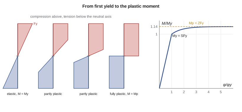
At \(M_p\) the curvature can increase almost without limit at constant moment. The beam has formed a plastic hinge, a short length that rotates like a rusty pin. In a simply supported beam one hinge forms a mechanism and the beam collapses. In a continuous beam, the first hinge, usually at a support, lets the moment redistribute to the spans until enough hinges form to create a mechanism. The extra capacity this gives is the basis of plastic analysis.
For W shapes bent about the strong axis, \(M_p\) is only 10 to 18 per cent above \(M_y\). The gap is small because the flanges, which carry most of the moment, are almost fully stressed at first yield. Designing to \(M_p\) uses that reserve rather than ignoring it.
Flexural resistance of laterally supported beams
When the compression flange is continuously supported, S16 gives the factored moment resistance by section class:
Class 4 sections, rare among rolled shapes, use an effective section modulus. The step from class 2 to class 3 is abrupt: a section just past the class 2 limit loses the whole shape factor. Tests show the real strength varies smoothly across the limit, so the rule is conservative for sections just past it, but it is simple and it is the rule used in this course.
Lateral support must be adequate. A metal deck welded or screwed to the top flange at close spacing, or a concrete slab with shear studs or embedded flanges, braces the compression flange of a simply supported beam. Near the supports of a continuous beam, however, the compression flange is the bottom flange, which the deck does not hold, so those regions need separate checks for lateral-torsional buckling (lesson 6).
Selecting a beam
For a laterally supported class 1 or 2 beam, the required plastic section modulus is \(Z_{req} = M_f/(\phi F_y)\). The CISC Handbook lists beams in order of mass for each \(Z_x\), with the lightest shape for a range of moments in bold. The lightest beam that satisfies strength is then checked for shear (lesson 7) and deflection. Deeper beams are usually lighter and stiffer for the same moment but cost headroom, and the depth may be limited by ceiling space and services.
Worked problem
Selecting the mezzanine beams
Select the lightest W shape for the mezzanine beams, \(M_f = 341\) kN·m, span 9.0 m, braced by the deck, and check the live load deflection against span/360 with \(w_L = 14.4\) kN/m.
Show solution
- Required modulus:
- \[Z_{req} = \frac{341 \times 10^6}{0.90(345)} = 1098 \times 10^3\ \text{mm}^3\]
- The W460x52 (\(Z_x = 1090 \times 10^3\) mm³) gives \(M_r = 338\) kN·m, just short. The W460x60 (\(Z_x = 1280 \times 10^3\) mm³, class 1 from lesson 2) gives
- \[M_r = 0.90(1280 \times 10^3)(345) = 397 \times 10^6\ \text{N·mm} = 397\ \text{kN·m} \ge 341\]
- Live load deflection with \(I_x = 255 \times 10^6\) mm⁴:
- \[\Delta_L = \frac{5w_LL^4}{384EI} = \frac{5(14.4)(9000)^4}{384(200\,000)(255 \times 10^6)} = 24.1\ \text{mm} \le \frac{9000}{360} = 25\ \text{mm}\]
Answer: Use W460x60 beams: \(M_r = 397\) kN·m against 341 kN·m, and the live load deflection of 24.1 mm is just inside span/360. The W410x60, with the same mass, has \(M_r = 371\) kN·m but deflects 28.5 mm, so the deeper section is the better choice.
Deflection and camber
Serviceability often controls steel floor beams, because high-strength steel lets a beam carry its moment at a depth too shallow to keep deflection small. Typical limits are span/360 for live load where partitions or brittle finishes are present and span/240 for total load. They protect finishes, keep floors level and avoid an impression of flexibility; they are not safety limits.
Camber, a slight upward curve put into the beam in the shop by cold bending, offsets the dead load deflection. It is specified when the dead load deflection would otherwise exceed about 20 mm or 3/4 in., and it is usually set at about 75 to 80 per cent of the calculated dead load deflection, because connections are never quite pinned and the beams do not deflect as much as calculated. Too much camber leaves a hump in the floor or makes the slab too thin at midspan.
For the W460x60, the dead load deflection is 16.2 mm and the total 40.3 mm, above span/240 = 37.5 mm. A 10 mm camber brings the net total to 30 mm. The slab must also be placed carefully: if the concrete is levelled to a flat top while the beam deflects under its weight, extra concrete ponds at midspan and adds load.
Floor vibration
Long-span steel floors with light concrete slabs can vibrate noticeably when people walk. The response depends on the natural frequency of the floor, which falls as deflection grows, and on its mass and damping. A rough guide is the frequency of a simply supported beam under its own sustained load, \(f \approx 0.18\sqrt{g/\Delta}\), with \(\Delta\) the deflection under dead load plus a small part of the live load. Floors with frequencies below about 8 to 9 Hz deserve a proper check by the methods in the CISC and AISC design guides. A storage mezzanine is less sensitive than an office, but people working at desks on a lively mezzanine notice it.
Plastic analysis of continuous beams
S16 permits plastic analysis for structures of class 1 sections that are adequately braced at the hinges and meet other conditions. In plastic analysis the collapse load is found from a mechanism with plastic hinges, and the factored loads are compared with it. For a two-span continuous beam with equal spans \(L\) under uniform load, the first hinges form at the interior support, and collapse occurs when a second hinge forms in each span about 0.414L from the end support:
The plastic collapse load is 46 per cent above the load at which an elastic analysis says the support moment reaches \(M_p\). The reserve comes from redistribution: after the support hinge forms, the spans keep carrying load until their own moments reach \(M_p\).
Worked problem
Capacity of an existing continuous beam
An existing two-span continuous W410x39 (\(Z_x = 724 \times 10^3\) mm³, class 1) with 6.0 m spans supports part of the old parts store. Compare its factored uniform load capacity by elastic and by plastic analysis.
Show solution
- \[M_r = 0.90(724 \times 10^3)(345) = 224.8\ \text{kN·m}\]
- \[w_{f,el} = \frac{8(224.8)}{6.0^2} = 50.0\ \text{kN/m} \qquad w_{f,pl} = \frac{11.66(224.8)}{6.0^2} = 72.8\ \text{kN/m}\]
Answer: Plastic analysis shows 46 per cent more capacity, provided the beam is braced at the hinges and its connections at the interior support can develop the hinge.
Sofia's program runs the beam selection over a short list of candidates, computes the deflections and camber, and repeats the continuous beam comparison.
# Mezzanine beam: laterally supported by the deck, class 1 or 2, CSA S16 clause 13.5
E, Fy, phi = 200000.0, 345.0, 0.90
L, Mf = 9000.0, 341.0                    # mm, kN.m (lesson 1)
wD, wL = 9.65, 14.4                      # kN/m = N/mm, specified loads
# name: (mass kg/m, Zx 1e3 mm3, Ix 1e6 mm4)
table = {"W410x46": (46, 885, 156), "W410x54": (54, 1049, 186), "W460x52": (52, 1090, 212),
         "W410x60": (60, 1196, 216), "W460x60": (60, 1280, 255), "W530x66": (66, 1560, 351)}
Zreq = Mf * 1e6 / (phi * Fy)
print(f"Z required = {Zreq/1e3:.0f} x 10^3 mm3")
for name, (m, Z, I) in sorted(table.items(), key=lambda kv: kv[1][0]):
    Mr = phi * Z * 1e3 * Fy / 1e6
    dL = 5 * wL * L**4 / (384 * E * I * 1e6)
    print(f"{name}: Mr = {Mr:5.0f} kN.m  {'OK ' if Mr >= Mf else 'NG '}  live deflection = {dL:5.1f} mm (limit {L/360:.0f})")

I = 255e6                                 # W460x60
dD = 5 * wD * L**4 / (384 * E * I)
dL = 5 * wL * L**4 / (384 * E * I)
print(f"W460x60: dead {dD:.1f} mm, live {dL:.1f} mm, total {dD+dL:.1f} mm (L/240 = {L/240:.1f})")
camber = 0.75 * dD
c = 5 * round(camber / 5)
print(f"Camber 75% of dead load deflection = {camber:.1f} mm, specify {c} mm; net total = {dD+dL-c:.1f} mm")

# Existing two-span continuous W410x39 (class 1), spans 6 m: elastic versus plastic capacity
Z39, Ls = 724e3, 6.0
Mr39 = phi * Z39 * Fy / 1e6
w_el = 8 * Mr39 / Ls**2
w_pl = 11.657 * Mr39 / Ls**2
print(f"W410x39: Mr = {Mr39:.1f} kN.m; elastic wf = {w_el:.1f} kN/m, plastic wf = {w_pl:.1f} kN/m (+{(w_pl/w_el-1)*100:.0f}%)")Z required = 1098 x 10^3 mm3 W410x46: Mr = 275 kN.m NG live deflection = 39.4 mm (limit 25) W460x52: Mr = 338 kN.m NG live deflection = 29.0 mm (limit 25) W410x54: Mr = 326 kN.m NG live deflection = 33.1 mm (limit 25) W410x60: Mr = 371 kN.m OK live deflection = 28.5 mm (limit 25) W460x60: Mr = 397 kN.m OK live deflection = 24.1 mm (limit 25) W530x66: Mr = 484 kN.m OK live deflection = 17.5 mm (limit 25) W460x60: dead 16.2 mm, live 24.1 mm, total 40.3 mm (L/240 = 37.5) Camber 75% of dead load deflection = 12.1 mm, specify 10 mm; net total = 30.3 mm W410x39: Mr = 224.8 kN.m; elastic wf = 50.0 kN/m, plastic wf = 72.8 kN/m (+46%)
Composite beams
The mezzanine beams are designed here as bare steel, with the slab only providing lateral support. If shear connectors, usually headed studs welded through the deck to the top flange, tie the slab to the beam, the two act together as a composite section. The slab becomes a wide compression flange, the plastic neutral axis moves up toward the top of the steel, and both strength and stiffness rise sharply, often by 50 per cent or more for the same steel beam. Composite design to S16 Clause 17 is the normal choice for office floors and is covered in a later course. The Kestrel Bay team chose non-composite beams for the mezzanine because the owner may want to remove or relocate the storage floor, and studs would make that harder; the cost is a slightly heavier beam.
Other bending cases
- Weak-axis bending: a W shape bent about its weak axis cannot buckle laterally, and its plastic modulus \(Z_y\) is about 1.5 times \(S_y\). The flanges must still meet the local buckling limits.
- Biaxial bending: roof purlins on a sloping roof bend about both axes. For laterally supported members the check is \(M_{fx}/M_{rx} + M_{fy}/M_{ry} \le 1.0\), and sag rods reduce the weak-axis span.
- Holes in the tension flange: bolt holes in a flange reduce its net area. S16 allows them to be ignored for flexure when the net flange area is not much less than the gross area, and otherwise the resistance is reduced.
- Ponding: on flat roofs, rainwater collecting in a deflected bay adds load that adds deflection. Roof framing must be stiff enough, or roofs must drain well enough, that ponding cannot become unstable.
Common mistakes
MistakeUsing \(Z\) for a class 3 section.
InsteadClass 3 sections are limited to \(M_y = SF_y\).
MistakeAssuming the deck braces the bottom flange near supports of continuous beams.
InsteadNegative moment regions need a lateral-torsional buckling check.
MistakeChecking deflection with factored loads.
InsteadDeflection is a serviceability check with specified loads.
MistakeCambering for the full calculated dead load deflection.
InsteadCamber about 75 to 80 per cent of it to avoid a hump in the floor.
Summary and key terms
- A laterally supported beam reaches the plastic moment \(M_p = ZF_y\) unless local buckling intervenes; \(M_p\) is about 1.1 to 1.2 times \(M_y\) for W shapes.
- S16: class 1 and 2, \(M_r = \phi ZF_y\); class 3, \(M_r = \phi SF_y\); \(\phi = 0.90\).
- Deflection often governs floor beams; camber offsets dead load deflection.
- Plastic analysis of continuous beams of compact or class 1 sections uses the reserve beyond first hinge formation; a two-span beam gains 46 per cent.
- The mezzanine beam is a W460x60: \(M_r = 397\) kN·m, live load deflection 24.1 mm, camber 10 mm.
- Yield moment
- My = SFy, the moment at which the extreme fibre first yields.
- Plastic moment
- Mp = ZFy, the moment at which the whole section has yielded.
- Plastic hinge
- A zone of a member that rotates at nearly constant moment Mp.
- Lateral support
- Restraint of the compression flange against sideways movement and twist.
- Camber
- An upward curvature built into a beam to offset dead load deflection.
- Mechanism
- A structure with enough plastic hinges to deform without further increase in load.
- Moment redistribution
- The shift of moment from yielded regions to regions with reserve strength.
- Ponding
- Accumulation of water on a deflecting roof that adds load and further deflection.
Practice problems
Work each problem on paper first, then reveal the answer to check.
Find \(M_r\) for a laterally supported W530x66 (\(Z_x = 1560 \times 10^3\) mm³).
Show answer
\(0.90(1560 \times 10^3)(345) = 484\) kN·m.
What uniform factored load can a simply supported, laterally supported W460x60 carry on an 8 m span?
Show answer
\(w_f = 8(397)/8^2 = 49.6\) kN/m, before checking shear and deflection.
Why is camber specified as a fraction of the calculated dead load deflection?
Show answer
Connections have some end restraint and the slab adds stiffness, so actual deflections are smaller than calculated.
Estimate the natural frequency of a beam whose sustained-load deflection is 20 mm.
Show answer
\(f \approx 0.18\sqrt{9810/20} = 4.0\) Hz, low enough to need a vibration check.
Lesson quiz · 5 questions
Score 60% or more to complete this lesson.
Create a free account to save your progress, take quizzes and earn a certificate.