
CIV-331 · Lesson 12 of 12 · 19 min
Design capstone: the maintenance bay
The earlier lessons designed the members and connections of the maintenance bay one at a time. A real design is more than a stack of member checks. It needs a consistent set of loads and load paths, members that suit fabrication and erection, connections that the shop can make and the field crew can bolt, protection against fire and corrosion, and drawings that tell everyone what to build. This capstone designs the last member, the monorail beam, assembles the member schedule, and walks through the review that Priya runs before the drawings are issued.
The monorail
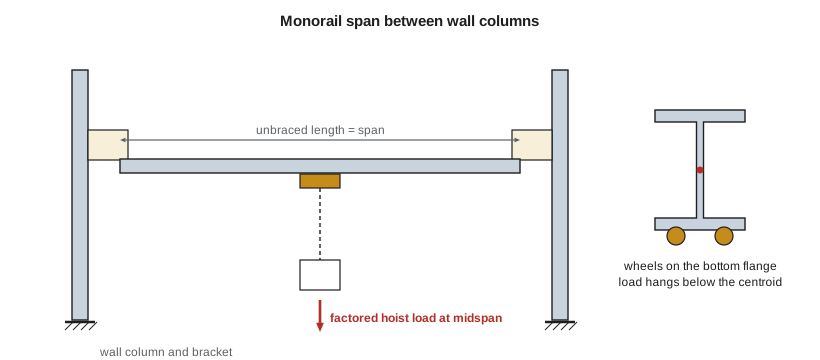
A 5-tonne electric hoist on a trolley runs along a monorail beam under the roof, so mechanics can lift engines and transmissions out of trucks and move them to the workbenches along the wall. The monorail is a W shape hung from brackets on the wall columns at 7.5 m centres, so each span is simply supported over 7.5 m. The hoist and trolley weigh 4.0 kN and the rated load is 49.0 kN. Moving loads on cranes and hoists are increased for impact; 25 per cent is a common allowance for powered hoists, and the factored load is treated like a live load:
The trolley wheels run on the bottom flange, so the load hangs below the shear centre, which is stabilizing for lateral-torsional buckling. It is conservative, and usual, to ignore that benefit. The beam is braced only at the brackets, so the unbraced length is the full span. Monorails also have a deflection limit tighter than floor beams, commonly about span/450 under the hoist and rated load without impact, so that the trolley does not run uphill and the load does not swing.
Worked problem
Selecting the monorail beam
Check a W310x60 and a W310x79 for the monorail: span 7.5 m, \(P_f = 99.4\) kN at midspan, \(\omega_2 = 1.26\), deflection limit span/450 under 53 kN.
Show solution
- W310x60 (\(Z_x = 934 \times 10^3\) mm³, \(I_y = 18.4 \times 10^6\) mm⁴, \(J = 377 \times 10^3\) mm⁴, \(C_w = 386 \times 10^9\) mm⁶):
- \[M_f = \frac{99.4(7.5)}{4} + \frac{1.25(0.59)(7.5)^2}{8} = 191.5\ \text{kN·m}\]
- With \(\omega_2 = 1.26\), \(M_u = 210\) kN·m, below \(M_p = 322\) kN·m, and the inelastic expression gives \(M_r = 189\) kN·m, 1 per cent short. Deflection: \(53\,000(7500)^3/(48 \times 200\,000 \times 127.8 \times 10^6) = 18.2\) mm = span/412, more than span/450.
- W310x79 (\(Z_x = 1280 \times 10^3\) mm³, \(I_x = 177 \times 10^6\) mm⁴):
- \[M_f = 193.2\ \text{kN·m} \qquad M_u = 424\ \text{kN·m} \qquad M_r = 324\ \text{kN·m}\]
- Deflection 13.2 mm = span/570.
Answer: The W310x60 fails narrowly in strength and misses the deflection target. Use W310x79: \(M_r = 324\) kN·m against 193 kN·m, deflection span/570. Its wider, thicker flange (254 mm wide, 14.6 mm thick) also suits the trolley wheels.
Three more checks complete the monorail. The bottom flange bends locally under the trolley wheels, like a short cantilever from the web; design guides for crane and monorail beams give the method, and flange thickness usually governs. The beam ends need stops so the trolley cannot run off. And the brackets and the wall columns that carry them must take the reaction, applied at an eccentricity from the column centreline.
The bracket reaction with the hoist at the support is about 103 kN, well below the 176 kN that the bolted bracket of lesson 9 can carry by the elastic method. The wall columns must now be rechecked as beam-columns with the bracket moment added to the wind and gravity effects of lesson 8, and with crane loads as one more load in the combinations.
The member schedule
Sofia's final program designs the monorail and prints the member schedule, with the governing limit state and utilization of each member. The schedule is the summary that Priya reviews and that goes into the design notes.
import math
# Monorail beam between wall columns: 7.5 m simple span, 5 t hoist, CSA S16
E, G, Fy, phi = 200000.0, 77000.0, 345.0, 0.90
L = 7500.0
rated, hoist = 49.0, 4.0                        # kN
P = 1.5 * 1.25 * (rated + hoist)                 # 25% impact, crane load factored like live load
shapes = {"W310x60": dict(m=0.59, Zx=934e3, Ix=127.8e6, Iy=18.4e6, J=377e3, Cw=386e9),
          "W310x79": dict(m=0.78, Zx=1280e3, Ix=177e6, Iy=39.9e6, J=658e3, Cw=848e9)}
w2 = 4 / math.sqrt(1 + 4 * 0.5**2 + 7 * 1 + 4 * 0.5**2)  # point load at midspan, load below shear centre ignored
for name, s in shapes.items():
    Mf = P * L / 4 / 1e3 + 1.25 * s["m"] * (L / 1e3)**2 / 8
    Mp = s["Zx"] * Fy / 1e6
    Mu = w2 * math.pi / L * math.sqrt(E * s["Iy"] * G * s["J"] + (math.pi * E / L)**2 * s["Iy"] * s["Cw"]) / 1e6
    Mr = min(1.15 * phi * Mp * (1 - 0.28 * Mp / Mu), phi * Mp) if Mu > 0.67 * Mp else phi * Mu
    defl = (rated + hoist) * 1e3 * L**3 / (48 * E * s["Ix"])
    print(f"{name}: Pf = {P:.1f} kN, Mf = {Mf:.1f} kN.m, Mu = {Mu:.0f}, Mr = {Mr:.0f} kN.m ({Mf/Mr:.2f}), "
          f"deflection {defl:.1f} mm = L/{L/defl:.0f}")
R = P + 1.25 * 0.78 * L / 2e3
print(f"Bracket reaction Rf = {R:.0f} kN (bolted bracket capacity from lesson 9: 176 kN elastic)")

print("\nMember schedule")
rows = [("Truss bottom chord", "2L102x102x9.5", "net fracture", 705 / 876),
        ("Mezzanine beam", "W460x60", "live load deflection", 24.1 / 25.0),
        ("Edge girder", "W530x74", "lateral-torsional buckling", 464 / 472),
        ("Mezzanine column", "W200x46", "flexural buckling", 890 / 920),
        ("Wall column", "W200x46", "beam-column, LTB", 0.58),
        ("Wall brace", "L89x89x6.4", "slenderness 274/300", 274 / 300),
        ("Beam connection", "2 clip angles, 3 M20", "block shear", 152 / 317)]
for member, size, gov, u in rows:
print(f" {member:20s} {size:22s} {gov:28s} {u:.2f}")W310x60: Pf = 99.4 kN, Mf = 191.5 kN.m, Mu = 210, Mr = 189 kN.m (1.01), deflection 18.2 mm = L/412 W310x79: Pf = 99.4 kN, Mf = 193.2 kN.m, Mu = 424, Mr = 324 kN.m (0.60), deflection 13.2 mm = L/570 Bracket reaction Rf = 103 kN (bolted bracket capacity from lesson 9: 176 kN elastic) Member schedule Truss bottom chord 2L102x102x9.5 net fracture 0.80 Mezzanine beam W460x60 live load deflection 0.96 Edge girder W530x74 lateral-torsional buckling 0.98 Mezzanine column W200x46 flexural buckling 0.97 Wall column W200x46 beam-column, LTB 0.58 Wall brace L89x89x6.4 slenderness 274/300 0.91 Beam connection 2 clip angles, 3 M20 block shear 0.48
A schedule like this shows at a glance where the design is tight and why. Several members are governed by something other than strength: deflection for the mezzanine beams, slenderness for the braces, and convenience for the wall columns, which repeat the mezzanine column size. That is normal in steel design. It also shows where a change would ripple: if the owner raises the mezzanine storage load, the beams, girders and columns are all close to their limits, but the braces and wall columns are not affected.
| Member | Size | Governing check | Utilization | Lesson |
|---|---|---|---|---|
| Truss bottom chord | 2L102x102x9.5 | Net fracture | 0.80 | 3 |
| Mezzanine column | W200x46 | Flexural buckling | 0.97 | 4 |
| Mezzanine beam | W460x60 | Live load deflection | 0.96 | 5 |
| Edge girder | W530x74 | Lateral-torsional buckling | 0.98 | 6 |
| Wall column | W200x46 | Beam-column, LTB | 0.58 | 8 |
| Beam connection | 2 clip angles, 3 M20 | Block shear | 0.48 | 9 |
| Wall brace | L89x89x6.4 | Slenderness 274/300 | 0.91 | 11 |
| Monorail | W310x79 | Deflection (span/570 against span/450) | 0.79 | 12 |
Weight, pieces and cost
Owen totals the steel: roughly 30 kg per square metre of floor and roof area for the bay, which is typical of a light industrial building with a storage mezzanine. Priya points out that the tonnage is only part of the story. Fabricators price steel by the piece and by the connection as much as by the tonne, so the decisions that saved the most money were not the lightest sections but the repeated ones: one beam size for every mezzanine bay, one column size for the mezzanine and the walls, one double-angle connection for every beam, and braces bolted with the same M20 bolts as everything else. Every unusual size or detail adds shop drawings, setups and the chance of an error.
The design review
Before the drawings are issued, Priya reviews the design against a checklist. The questions are general enough to use on any steel building:
- Loads: are all load cases and combinations included, including snow drifts at the step from the office wing to the garage, crane loads, notional loads and construction loads?
- Load paths: does every force, gravity and lateral, have a complete path to the foundations, including diaphragms, collectors, braces and anchor rods?
- Stability: is every compression member and every compression flange braced, and are the braces strong and stiff enough? Is the structure stable during erection?
- Members: are the governing limit states identified, including serviceability, and do the utilizations make sense?
- Connections: are the connection forces stated on the drawings for the connection designer, and are the connection types consistent with the analysis model?
- Constructability: are sizes repeated, connections standard, field welding avoided and clearances adequate for erection and bolting?
- Durability and fire: are the coating system and any fire protection specified?
- Independent check: has another engineer checked the key calculations and the drawings? Independent checking is the most effective way to catch errors, including errors in software input.
Fire, corrosion and durability
The NBC sets fire-resistance ratings by building size, occupancy and sprinklers. A one-storey sprinklered garage of this size can often use unprotected steel, but the mezzanine and its supports may need a rating, achieved with sprayed fire-resistive material, intumescent paint or board encasement, or with a rational fire design. The steel in a vehicle maintenance bay sees salt-laden slush from trucks in winter. The team specifies hot-dip galvanizing for the wall columns, the column bases and the lowest girts, and a shop primer and finish coat elsewhere. Details avoid pockets that trap water and salt, and the column bases sit on concrete piers above the slab.
Drawings, shop drawings and construction
The structural drawings show the framing plans and elevations, member sizes, the steel grades and bolt types, the coating and fire protection, the connection forces and types, the camber of the mezzanine beams, and notes on erection bracing and the lateral system. The fabricator's detailer prepares shop and erection drawings, which the team reviews. During construction, inspection checks the material certificates, the bolt installation and the welds, and the engineer visits the site at key stages: after the columns and braces are set, when the trusses are erected, and before the mezzanine slab is placed.
Erection follows a sequence that keeps the frame stable: set the wall columns on their anchor rods, install the braced bays first, then the roof trusses and their bracing, then the deck; set the mezzanine columns, girders and beams, bolt the connections, and place the deck and slab. The erector's engineer plans temporary bracing for wind during erection, when the structure has none of its finished stiffness.
What you can now do
With the methods of this course you can design the main members and connections of a typical steel building: tension members by gross yielding, net fracture and block shear; columns by the column curve; beams by plastic moment, local buckling and lateral-torsional buckling, with shear, web bearing and deflection; beam-columns by interaction with amplification; bolted and welded connections, including eccentric groups; and the bracing and stability of the frame. Later courses add composite construction, plate girders, connections for moment frames, seismic design and steel bridges, all built on the same limit states and the same habits of checking every load path.
Common mistakes
MistakeDesigning the monorail for the rated load alone.
InsteadAdd the hoist weight and the impact allowance, and use a tighter deflection limit.
MistakeAssuming a member schedule is complete when every member passes.
InsteadThe review also checks load paths, stability, connections, constructability, durability and fire.
MistakeLeaving connection forces off the drawings.
InsteadThe connection designer and detailer need the forces for every connection.
MistakeIgnoring erection stability.
InsteadPlan the erection sequence and temporary bracing; the frame is weakest before the deck and braces are installed.
Summary and key terms
- The monorail is a W310x79, chosen over the W310x60 for strength and the span/450 deflection target.
- Crane and hoist loads include the hoist weight and an impact allowance, and need tighter deflection limits.
- A member schedule with governing limit states and utilizations summarizes the design and shows where it is tight.
- The design review checks loads, load paths, stability, members, connections, constructability, durability, fire and independent checking.
- Erection sequence and temporary bracing keep the frame stable before it is complete.
- Monorail
- A single beam on which a hoist trolley runs.
- Impact allowance
- An increase in moving crane or hoist loads to account for dynamic effects.
- Member schedule
- A table of members with their sizes, governing checks and utilizations.
- Utilization
- The ratio of a load effect to the corresponding resistance.
- Erection drawings
- Drawings that show how and in what order members are assembled on site.
- Hot-dip galvanizing
- Coating steel with zinc by immersion in molten zinc for corrosion protection.
- Sprayed fire-resistive material
- A sprayed coating that insulates steel from fire.
- Independent check
- A review of calculations and drawings by an engineer not involved in the original design.
Practice problems
Work each problem on paper first, then reveal the answer to check.
If the hoist capacity rises to 7.5 t (73.5 kN), what is the new \(P_f\)?
Show answer
\(1.5(1.25)(73.5 + 4.0) = 145\) kN; the W310x79 would need rechecking.
Why is it conservative to ignore the stabilizing effect of a bottom-flange load?
Show answer
The critical moment is higher when the load hangs below the shear centre, so ignoring this underestimates the resistance.
Which members of the maintenance bay would change if the mezzanine storage load doubled?
Show answer
The mezzanine beams, girders, columns and connections; the braces, truss and wall columns would not.
Name two ways to give the mezzanine steel a fire-resistance rating.
Show answer
Sprayed fire-resistive material, intumescent coating, board encasement, or a rational or performance-based fire design.
Lesson quiz · 5 questions
Score 60% or more to complete this lesson.
Create a free account to save your progress, take quizzes and earn a certificate.