
CIV-224 · Lesson 12 of 12 · 26 min
Introduction to indeterminate structures: the force method
Most real structures are statically indeterminate. Continuous beams run over several supports, building frames have rigid joints and fixed or pinned bases on both sides, and trusses often have extra members. Indeterminate structures have more unknown forces than equilibrium equations, so statics alone cannot find them. The missing equations come from compatibility: the requirement that the deformed structure fits together and respects its supports. This lesson introduces the oldest systematic approach, the force method, which uses exactly the deflection tools of lessons 10 and 11. CIV-321 continues with the slope-deflection, moment distribution and matrix stiffness methods.
Why build indeterminate structures?
Redundancy brings real advantages. For the same loads and spans, indeterminate structures generally have smaller maximum moments and deflections, because continuity lets adjacent spans help each other. A two-span continuous beam under uniform load has a maximum moment of \(wL^2/8\) over the middle support, the same as a simple span, but its span moments drop to about 56 per cent of the simple-span value, and its deflections drop by more than half. Indeterminate structures also have alternative load paths. If one member is damaged by a vehicle impact, fire or corrosion, the load can redistribute to others instead of causing collapse, a property engineers call robustness.
There are costs. Because internal forces depend on relative stiffness, the analysis is more involved and must be repeated if member sizes change. Indeterminate structures also develop internal forces from effects that cause no forces in determinate ones: support settlement, temperature change, shrinkage, and fabrication misfit. A continuous beam whose middle support settles redistributes its moments, and a fixed arch heated by the sun develops bending. The designer must account for these effects, or choose a determinate form, such as the three-hinged frames of the salt shed, where foundations are uncertain.
The idea of the force method
The force method, also called the flexibility or consistent deformation method, works by turning an indeterminate structure into a determinate one and then restoring compatibility.
- Determine the degree of indeterminacy n and choose n redundants: reactions or internal forces whose removal leaves a stable determinate structure, called the primary or released structure.
- Compute the displacements of the primary structure, at the location and in the direction of each redundant, caused by the actual loads.
- Compute the displacements of the primary structure caused by a unit value of each redundant acting alone. These are flexibility coefficients: \(f_{ij}\) is the displacement at redundant i caused by a unit value of redundant j.
- Write one compatibility equation for each redundant, stating that the total displacement at that location equals its known value (usually zero at a support): \(\Delta_{i0} + \sum_j f_{ij}X_j = \Delta_i\).
- Solve for the redundants, then find all other forces by equilibrium, which is now possible because the redundants are known.
One redundant: the propped cantilever
Worked problem
A propped cantilever under uniform load
A beam of span L and constant EI is fixed at A and supported on a roller at B, and carries a uniform load w. Find the reaction at B and the fixed-end moment.
Show solution
- Degree of indeterminacy: \(r = 4\), so \(n = 1\). Choose the roller reaction \(R_B\) as the redundant; removing it leaves a cantilever.
- Deflection of the cantilever tip due to the load (lesson 10), downward: \(\Delta_{B0} = wL^4/(8EI)\).
- Deflection of the tip due to a unit upward force: \(f_{BB} = L^3/(3EI)\), upward.
- Compatibility: the tip does not move, so \(-\dfrac{wL^4}{8EI} + R_B\dfrac{L^3}{3EI} = 0\).
- \[R_B = \frac{3wL}{8} \qquad R_A = \frac{5wL}{8} \qquad M_A = R_B L - \frac{wL^2}{2} = -\frac{wL^2}{8}\]
Answer: The roller carries three-eighths of the load and the fixed end five-eighths, with a hogging moment of \(wL^2/8\) at the fixed end. The maximum sagging moment, \(9wL^2/128\), occurs at \(3L/8\) from B.
Continuous beams
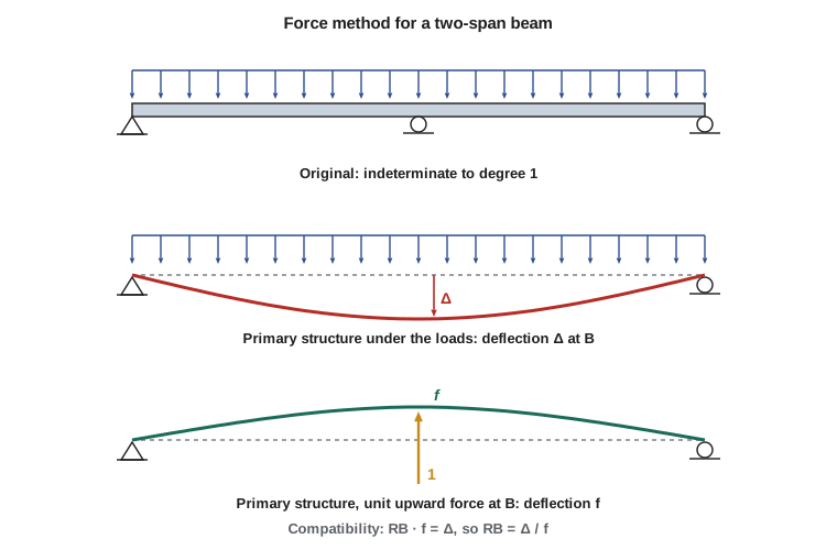
A beam continuous over two spans has one redundant reaction. Removing the middle support leaves a simple beam spanning both spans, whose midspan deflection under the load is easy to compute. A unit upward force at the middle support of that simple beam produces the flexibility coefficient, and compatibility gives the middle reaction.
Worked problem
A two-span continuous floor beam
In the office wing, a floor beam is continuous over two equal spans of 7.5 m, with supports A, B and C. It carries a factored uniform load of 19.0 kN/m and has constant EI. Find the reactions, the moment over B and the maximum span moment, and compare them with two simple spans.
Show solution
- Redundant: \(R_B\). The primary structure is a simple beam of span 2L.
- Deflection at B due to the load: \(\Delta_{B0} = \dfrac{5w(2L)^4}{384EI} = \dfrac{5wL^4}{24EI}\) downward.
- Deflection at B due to a unit upward force: \(f_{BB} = \dfrac{(2L)^3}{48EI} = \dfrac{L^3}{6EI}\) upward.
- \[R_B = \frac{\Delta_{B0}}{f_{BB}} = \frac{5wL^4/24}{L^3/6} = \frac{5wL}{4}\]
- By symmetry and vertical equilibrium, \(R_A = R_C = (2wL - 5wL/4)/2 = 3wL/8\).
- Numbers: \(wL = 19.0 \times 7.5 = 142.5\ \text{kN}\), so \(R_B = 178\ \text{kN}\) and \(R_A = R_C = 53.4\ \text{kN}\). The moment over B is \(M_B = R_A L - wL^2/2 = 53.4(7.5) - 19.0(7.5^2)/2 = 400.8 - 534.4 = -134\ \text{kN·m}\), which equals \(-wL^2/8\). The maximum positive moment is \(R_A^2/(2w) = 53.4^2/38 = 75.1\ \text{kN·m}\), at \(3L/8 = 2.81\ \text{m}\) from A.
Answer: Compared with two simple spans (reactions 71.3 kN, 142.5 kN and 71.3 kN; span moments 134 kN·m), continuity moves load toward the middle support, keeps the peak moment the same but moves it over the support, and cuts the span moments to 56 per cent. The middle support must be designed for 178 kN instead of 142.5 kN, a 25 per cent increase.
The moment over the middle support is the same as each simple span's moment, so the continuous beam needs the same section, but its deflection is much smaller: for one span of a two-span beam under full load, the maximum deflection is about \(wL^4/(185EI)\) instead of \(5wL^4/(384EI) = wL^4/(77EI)\). That gain in stiffness is why continuous construction is standard for floor beams, bridge girders and slabs.
Maxwell's reciprocal theorem
With two or more redundants, the compatibility equations form a system \(\sum_j f_{ij}X_j = \Delta_i - \Delta_{i0}\), and you need all the flexibility coefficients. James Clerk Maxwell proved in 1864 that for a linearly elastic structure \(f_{ij} = f_{ji}\): the displacement at point i due to a unit load at j equals the displacement at j due to a unit load at i. The flexibility matrix is therefore symmetric, which halves the work and provides a check on the arithmetic. Betti later generalized the theorem to any two load systems: the work done by the first set of loads acting through the displacements caused by the second equals the work done by the second set through the displacements caused by the first.
The reciprocal theorem also explains the Müller-Breslau principle of lesson 8. The influence line for a reaction is the deflected shape when that reaction is released and displaced by one unit, because, by reciprocity, the reaction caused by a unit load at x equals the deflection at x caused by a unit displacement of the released support, scaled appropriately.
Support settlement and temperature
The compatibility equation also handles known support movements. If the middle support of the two-span beam settles by \(\delta\), compatibility becomes \(-\Delta_{B0} + R_B f_{BB} = -\delta\), so the middle reaction drops by \(\delta/f_{BB} = 6EI\delta/L^3\), and the end reactions increase to keep equilibrium. Stiff beams on short spans are the most sensitive, because \(6EI/L^3\) is large.
Worked problem
Effect of settlement on the continuous beam
The two-span beam is a W530×66 with \(EI \approx 70\,200\ \text{kN·m}^2\). If the middle footing settles 10 mm more than the end supports, how much do the reactions and the moment over B change?
Show solution
- \[\Delta R_B = \frac{6EI\delta}{L^3} = \frac{6(70\,200)(0.010)}{7.5^3} = \frac{4212}{421.9} = 10.0\ \text{kN}\ \text{(decrease)}\]
- Each end reaction increases by 5.0 kN.
- The moment over B changes by \(\Delta R_A \times L = 5.0 \times 7.5 = 37.5\ \text{kN·m}\), from \(-134\) to about \(-96\ \text{kN·m}\), while the span moments grow.
Answer: A modest 10 mm settlement shifts the moment over the support by more than a quarter. Geotechnical estimates of differential settlement are therefore part of the structural design of continuous members, and for very soft ground a determinate layout may be the better choice.
Temperature effects enter the same way. A uniform temperature change in a beam on rollers causes no force, but if both ends are restrained, the free expansion \(\alpha\,\Delta T\,L\) must be cancelled by an axial force, which compatibility gives as \(EA\,\alpha\,\Delta T\). A temperature difference between the top and bottom of a continuous beam, as under strong sun, causes curvature that the intermediate supports resist, producing moments that a determinate beam would not have.
Choosing redundants and looking ahead
Any set of redundants that leaves a stable primary structure works, but a good choice simplifies the computation. Removing interior supports of a continuous beam leaves a simple beam whose deflections are standard formulas. Inserting hinges over the supports instead, so that the redundants are the support moments, leaves a series of simple spans whose flexibility coefficients involve only adjacent spans, which gives a banded system of equations, the three-moment equation of Clapeyron. For a frame, cutting each closed loop releases three internal forces.
The force method becomes cumbersome for structures with many redundants, because each needs its own displacement calculations and the equations are coupled. The displacement (stiffness) methods take the opposite approach: they treat the joint displacements as unknowns and write equilibrium equations at the joints. That is the basis of moment distribution, slope-deflection, and the matrix stiffness method used by every structural analysis program today. You will study them in CIV-321, but the ideas of this course (equilibrium, compatibility, and the link between forces and deformations) remain the foundation.
The force method by computer
Sofia's program applies the force method to a two-span beam with any uniform loads on the spans, computing the deflections of the primary structure by numerical integration of \(mM/(EI)\), exactly as in lesson 11, rather than from formulas. It then checks the classic results and adds the settlement case.
# Two-span continuous beam A-B-C by the force method; redundant = reaction at B
L1, L2 = 7.5, 7.5                  # spans (m)
w1, w2 = 19.0, 19.0                # factored uniform loads (kN/m)
EI = 70200.0                       # kN*m^2
settle = 0.0                       # settlement of B (m), downward positive
Lt = L1 + L2

def M0(x):                         # primary structure (simple beam A-C) moment from loads
    RA = (w1 * L1 * (Lt - L1 / 2) + w2 * L2 * (L2 / 2)) / Lt
    m = RA * x - w1 * min(x, L1) * (x - min(x, L1) / 2)
    if x > L1: m -= w2 * (x - L1) ** 2 / 2
    return m

def m1(x):                         # moment from a unit upward force at B
    RA = -L2 / Lt
    return RA * x + (x - L1 if x > L1 else 0.0)

n = 6000; h = Lt / n
xs = [i * h for i in range(n + 1)]
def integ(f):
    return sum((f(xs[i]) + f(xs[i + 1])) / 2 * h for i in range(n))
D0 = integ(lambda x: m1(x) * M0(x)) / EI          # upward displacement at B due to loads
f11 = integ(lambda x: m1(x) ** 2) / EI            # upward displacement due to unit upward force
for s in (0.0, 0.010):
    RB = (-s - D0) / f11
    RA = ((w1 * L1 * (Lt - L1 / 2) + w2 * L2 * L2 / 2) - RB * L2) / Lt
    MB = RA * L1 - w1 * L1 ** 2 / 2
    print(f"settlement {s*1000:4.0f} mm: RB = {RB:6.1f} kN, RA = {RA:5.1f} kN, MB = {MB:7.1f} kN*m")
print(f"check 5wL/4 = {1.25 * w1 * L1:.1f} kN, -wL^2/8 = {-w1 * L1**2 / 8:.1f} kN*m")settlement 0 mm: RB = 178.1 kN, RA = 53.4 kN, MB = -133.6 kN*m settlement 10 mm: RB = 168.1 kN, RA = 58.4 kN, MB = -96.2 kN*m check 5wL/4 = 178.1 kN, -wL^2/8 = -133.6 kN*m
Changing one span's load to zero gives the pattern-loading case for maximum positive moment in the other span, which lesson 8's Müller-Breslau sketch predicted. With unequal spans or loads, the program still works, because nothing in it assumes symmetry.
Common mistakes
MistakeChoosing redundants that leave an unstable primary structure.
InsteadCheck the primary structure for stability before computing anything.
MistakeMixing up the signs of the load displacement and the flexibility coefficient.
InsteadMeasure both in the direction of the assumed redundant; the compatibility equation then sums them directly.
MistakeIgnoring support settlement and temperature in indeterminate structures.
InsteadThey cause internal forces; include them in the compatibility equations.
MistakeAssuming continuity always reduces the governing moment.
InsteadFor equal spans under full uniform load the peak moment stays at \(wL^2/8\); continuity reduces span moments and deflections, not necessarily the peak.
Summary and key terms
- Indeterminate structures need compatibility equations in addition to equilibrium.
- Force method: release n redundants, compute primary displacements, write \(\Delta_{i0} + \sum f_{ij}X_j = \Delta_i\), solve.
- Propped cantilever under uniform load: \(R = 3wL/8\), fixed-end moment \(wL^2/8\).
- Two equal spans under uniform load: \(R_B = 5wL/4\), \(M_B = -wL^2/8\), span moment \(9wL^2/128\).
- Maxwell's reciprocal theorem: \(f_{ij} = f_{ji}\), so flexibility matrices are symmetric.
- Settlement and temperature change cause forces in indeterminate structures; displacement methods (CIV-321) are used for larger problems.
- Redundant
- A reaction or internal force chosen as an unknown in the force method.
- Primary structure
- The determinate structure left after the redundants are released.
- Compatibility
- The requirement that deformations be consistent with supports and continuity.
- Flexibility coefficient
- The displacement at one point caused by a unit force at another.
- Force method
- Analysis of indeterminate structures with redundant forces as unknowns.
- Maxwell's reciprocal theorem
- The displacement at i due to a unit load at j equals the displacement at j due to a unit load at i.
- Robustness
- The ability of a structure to withstand local damage without disproportionate collapse.
- Stiffness method
- Analysis with joint displacements as unknowns, used in structural software.
Practice problems
Work each problem on paper first, then reveal the answer to check.
What is the degree of indeterminacy of a beam continuous over four supports (pin and three rollers)?
Show answer
\(r = 5\): degree 2.
A propped cantilever of span 6 m carries 10 kN/m. Find the prop reaction and the fixed-end moment.
Show answer
\(R = 3(10)(6)/8 = 22.5\ \text{kN}\); \(M = 10(36)/8 = 45\ \text{kN·m}\) hogging.
State Maxwell's reciprocal theorem.
Show answer
For a linear elastic structure, the displacement at i due to a unit load at j equals the displacement at j due to a unit load at i.
Why does support settlement cause forces in a continuous beam but not in a simple beam?
Show answer
The continuous beam is indeterminate, so the settlement violates compatibility unless forces develop; a simple beam just moves as a rigid body.
In the force method for a two-span beam with the middle support as redundant, what is the primary structure?
Show answer
A simple beam spanning both spans.
Which methods do structural analysis programs use?
Show answer
Displacement (stiffness) methods, usually the matrix stiffness or finite element method.
Lesson quiz · 5 questions
Score 60% or more to complete this lesson.
Create a free account to save your progress, take quizzes and earn a certificate.