
CIV-224 · Lesson 10 of 12 · 29 min
Deflections by integration and moment-area
A structure can be strong enough and still unacceptable if it deflects too much. Floors that sag crack partitions and ceilings, roofs that sag pond water and attract more load, crane runways that deflect make cranes bind, and frames that sway damage cladding and alarm occupants. Building codes and design standards therefore set serviceability limits on deflection. Computing deflections is also the key to analysing indeterminate structures in lesson 12, where compatibility of displacements supplies the extra equations that equilibrium cannot. This lesson covers two classical methods for beams: double integration, which you met in mechanics of solids, and the moment-area method, which is often faster.
The elastic curve
For small deflections of a linearly elastic beam, the curvature of the deflected axis (the elastic curve) is proportional to the bending moment:
where v is the deflection (positive upward in this lesson), E is the modulus of elasticity and I the second moment of area about the bending axis. The product EI is the flexural rigidity. The equation neglects shear deformation, which is a good approximation for ordinary beams whose span is more than about ten times their depth, and assumes slopes small enough that the square of the slope is negligible compared with 1, which holds for virtually all real structures.
Two pieces of information come straight from the moment diagram. Where M is positive the beam is concave upward; where it is negative, concave downward; and at a point of inflection the curvature is zero. Before calculating any deflection, sketch the deflected shape from the moment diagram and the support conditions. The sketch catches sign errors and shows where the maximum deflection is likely to be.
Double integration
Integrating the moment-curvature equation once gives the slope \(\theta = dv/dx\), and twice gives the deflection, with two constants of integration found from boundary conditions: zero deflection at a pin or roller, zero deflection and zero slope at a fixed support. If the moment expression changes along the beam, at point loads or where a distributed load starts or stops, each segment has its own equation and two constants, and continuity of slope and deflection at the segment boundaries supplies the extra conditions. For a beam with several loads the bookkeeping grows quickly, which is why other methods are useful.
Worked problem
A cantilever under uniform load
A cantilever of length L, fixed at A (x = 0) and free at B, carries a uniform load w. Find the slope and deflection at the tip.
Show solution
- Taking the part to the right of a section at x: \(M = -w(L - x)^2/2\).
- \[EI\,v'' = -\frac{w}{2}(L - x)^2\]
- \[EI\,v' = \frac{w}{6}(L - x)^3 + C_1 \qquad EI\,v = -\frac{w}{24}(L - x)^4 + C_1 x + C_2\]
- At the fixed end \(v'(0) = 0\), so \(C_1 = -wL^3/6\); and \(v(0) = 0\), so \(C_2 = wL^4/24\).
- At the tip, \(x = L\): \(EI\,\theta_B = -wL^3/6\) and \(EI\,v_B = -wL^3/6 \cdot L + wL^4/24 = -wL^4/8\).
Answer: The tip rotates \(wL^3/(6EI)\) and deflects \(wL^4/(8EI)\) downward, two results worth memorizing along with the simply supported beam's \(5wL^4/(384EI)\) and the tip-loaded cantilever's \(PL^3/(3EI)\).
The moment-area theorems
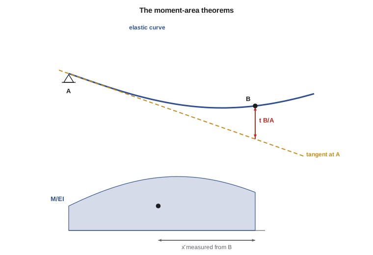
Otto Mohr and Charles Greene, independently, developed in the 1870s a geometric way to use the moment-curvature relation without writing equations for every segment. Plot the \(M/EI\) diagram, which for a beam of constant EI is just the moment diagram divided by EI. Then two theorems relate the elastic curve between any two points A and B to the area of that diagram.
- First moment-area theorem: the change in slope between A and B equals the area of the \(M/EI\) diagram between them: \(\theta_B - \theta_A = \int_A^B (M/EI)\,dx\).
- Second moment-area theorem: the vertical distance from point B on the elastic curve to the tangent drawn at A, called the tangential deviation \(t_{B/A}\), equals the first moment of the \(M/EI\) area between A and B taken about B: \(t_{B/A} = \int_A^B (M/EI)\,\bar{x}_B\,dx\), where \(\bar{x}_B\) is measured from B.
The order of the subscripts matters. \(t_{B/A}\) is the deviation of B from the tangent at A, and its moment arm is measured from B. It is positive when B lies above the tangent at A, which happens when the \(M/EI\) area is positive. The theorems need only areas and centroids, so moment diagrams drawn by parts (lesson 5) make them quick.
Using the theorems
The strategy is to find a tangent of known direction and then measure deviations from it. In a cantilever, the tangent at the fixed end is horizontal, so the deflection anywhere equals the tangential deviation from that tangent. In a symmetric simply supported beam with symmetric loading, the tangent at midspan is horizontal, so the midspan deflection equals the deviation of a support from the midspan tangent. In unsymmetric cases, draw the tangent at one support, find the deviation of the other support from it, and use similar triangles to locate the tangent, as the conjugate beam method below automates.
Worked problem
Tip deflection of a cantilever with a point load
A cantilever of length L, fixed at A, carries a point load P at the free end B. Find the tip deflection by moment-area.
Show solution
- The moment diagram is a triangle from \(-PL\) at A to zero at B, so the \(M/EI\) area is \(-\tfrac{1}{2}L \cdot PL/EI = -PL^2/(2EI)\), with its centroid \(2L/3\) from B.
- The tangent at A is horizontal, so the tip deflection equals \(t_{B/A}\):
- \[t_{B/A} = -\frac{PL^2}{2EI}\cdot\frac{2L}{3} = -\frac{PL^3}{3EI}\]
- The tip slope is the area itself, \(-PL^2/(2EI)\) (clockwise).
Answer: The tip deflects \(PL^3/(3EI)\) downward. With moment-area this took three lines; double integration takes about ten.
Worked problem
Midspan deflection of the office girder
The office wing girder from lesson 5 spans 7.5 m with equal loads at its third points. Under specified live load each point load is \(P = 6.0 \times 7.5/2 \times 2 = 45\ \text{kN}\). The girder is a W530×66 with \(I \approx 351 \times 10^6\ \text{mm}^4\) and \(E = 200\ \text{GPa}\). Find the midspan live load deflection and compare it with span/360.
Show solution
- By symmetry the tangent at midspan C is horizontal, so the midspan deflection equals \(t_{A/C}\), the deviation of A from that tangent, with moments taken about A.
- Between A and C the moment diagram is a triangle from 0 to \(Pa\) over \(a = L/3\), then a rectangle of height \(Pa\) from \(L/3\) to \(L/2\).
- \[EI\,t_{A/C} = \frac{Pa^2}{2}\cdot\frac{2a}{3} + Pa\Big(\frac{L}{2} - a\Big)\Big(a + \frac{L/2 - a}{2}\Big) = \frac{PL^3}{81} + \frac{5PL^3}{216} = \frac{23PL^3}{648}\]
- Numerically: \(\Delta = \dfrac{23(45\,000)(7500)^3}{648(200\,000)(351 \times 10^6)} = 9.6\ \text{mm}\).
- Limit: \(7500/360 = 20.8\ \text{mm}\).
Answer: The live load deflection of 9.6 mm is less than half the 20.8 mm limit, so the girder chosen for strength easily satisfies serviceability. A shallower girder might not.
Unsymmetric beams and overhangs
When the tangent of known direction is not obvious, work from a support. For a simply supported beam AB, draw the tangent at A. The deviation \(t_{B/A}\) is the distance from B, which does not move, to that tangent; dividing it by the span gives the slope at A. Then the deflection at any point C is the distance from the chord AB to the tangent at A, minus \(t_{C/A}\). For an overhang beyond B, extend the same tangent: the tip deflection is the tangent's offset at the tip, found by similar triangles, minus the tip's deviation from the tangent at A. It sounds involved, but each step is a single area-times-distance product, and a sketch of the tangent lines keeps the signs straight.
The conjugate beam method
The moment-area theorems can be packaged into an analogy that turns deflection problems into familiar shear and moment problems. Load an imaginary conjugate beam, of the same length as the real one, with the \(M/EI\) diagram as a distributed load. Then the shear in the conjugate beam at any point equals the slope of the real beam, and the bending moment in the conjugate beam equals the real beam's deflection. The supports of the conjugate beam are chosen so that these correspondences hold: a real pin or roller (zero deflection, slope free) becomes a conjugate pin or roller; a real fixed end (zero slope and deflection) becomes a conjugate free end; a real free end becomes a conjugate fixed end; and an interior support becomes an internal hinge, while an internal hinge becomes an interior support.
For a simply supported beam with a uniform load, the conjugate beam is also simply supported and carries a parabolic load of peak \(wL^2/(8EI)\). Its reaction, \(wL^3/(24EI)\), is the end slope of the real beam, and its midspan moment, \(5wL^4/(384EI)\), is the real midspan deflection. The method shines for beams with varying EI, such as haunched girders or beams with cover plates, where the \(M/EI\) diagram has steps that double integration would have to handle segment by segment.
Worked problem
A beam with a stiffer central portion
A simply supported beam of span L carries a point load P at midspan. Its middle half has a cover plate that doubles its moment of inertia to 2I; the outer quarters have I. Find the midspan deflection and compare it with the uniform beam.
Show solution
- The moment diagram is a triangle with peak \(PL/4\) at midspan. Dividing by EI, the outer quarters keep their full value, rising to \(PL/(8EI)\) at the quarter points, while the middle half is halved, running from \(PL/(16EI)\) at the quarter points to \(PL/(8EI)\) at midspan.
- By symmetry the tangent at midspan is horizontal; take moments of the \(M/EI\) area between A and midspan about A.
- Outer quarter: triangle of base \(L/4\), height \(PL/(8EI)\), area \(PL^2/(64EI)\), centroid \(L/6\) from A: moment \(PL^3/(384EI)\).
- Middle part, as a rectangle of height \(PL/(16EI)\) over \(L/4\) (area \(PL^2/(64EI)\), centroid \(3L/8\)) plus a triangle of height \(PL/(16EI)\) (area \(PL^2/(128EI)\), centroid \(L/4 + 2L/12 = 5L/12\)): moments \(3PL^3/(512EI)\) and \(5PL^3/(1536EI)\).
- \[\Delta = \frac{PL^3}{EI}\Big(\frac{1}{384} + \frac{3}{512} + \frac{5}{1536}\Big) = \frac{PL^3}{EI}\cdot\frac{4 + 9 + 5}{1536} = \frac{18\,PL^3}{1536\,EI} = \frac{3PL^3}{256\,EI}\]
Answer: The midspan deflection is \(3PL^3/(256EI) = 0.0117\,PL^3/EI\), compared with \(PL^3/(48EI) = 0.0208\,PL^3/EI\) for the uniform beam: the cover plates cut the deflection by about 44 per cent while adding steel only where the moment is high.
Deflections by numerical integration
For awkward loadings or varying stiffness, numerical integration of the curvature works for any determinate beam. Sofia's program computes the moment at many points, integrates curvature twice with the trapezoidal rule from an arbitrary starting slope, and then corrects with a straight line so that the deflection is zero at both supports. Applied to the canopy beam of lesson 5, it gives the deflection at midspan and at the overhang tip.
# Canopy beam: pin A (x=0), roller B (x=6), overhang to C (x=8); specified uniform load
w, Lab, Lt = 7.0, 6.0, 8.0                   # kN/m, m
E, I = 200e6, 60e-6                          # kN/m^2 and m^4 (EI = 12,000 kN*m^2)
RB = w * Lt * (Lt / 2) / Lab; RA = w * Lt - RB

def M(x):
    m = RA * x - w * x * x / 2
    if x > Lab: m += RB * (x - Lab)
    return m

n = 8000; h = Lt / n
xs = [i * h for i in range(n + 1)]
kappa = [M(x) / (E * I) for x in xs]
slope = [0.0]; v = [0.0]
for i in range(n):                          # integrate from x = 0 with zero trial slope
    slope.append(slope[-1] + (kappa[i] + kappa[i + 1]) / 2 * h)
    v.append(v[-1] + (slope[i] + slope[i + 1]) / 2 * h)
iB = int(round(Lab / h))
c = -v[iB] / Lab                            # rotate so that v(B) = 0
v = [vi + c * x for vi, x in zip(v, xs)]
imid = int(round(Lab / 2 / h))
vmin = min(v[:iB + 1])
print(f"RA = {RA:.2f} kN, RB = {RB:.2f} kN")
print(f"Deflection at midspan of AB: {v[imid] * 1000:7.2f} mm")
print(f"Largest downward deflection in AB: {vmin * 1000:7.2f} mm")
print(f"Deflection at tip C: {v[-1] * 1000:7.2f} mm (positive = upward)")RA = 18.67 kN, RB = 37.33 kN Deflection at midspan of AB: -7.22 mm Largest downward deflection in AB: -7.24 mm Deflection at tip C: 4.67 mm (positive = upward)
The tip of the overhang moves up while the span sags, because the span's sagging rotates the beam about B and lifts the short overhang more than the overhang's own load pushes it down. That matches the sketch you could have drawn from the moment diagram, and it is exactly the kind of result that is easy to get backwards by hand.
Common mistakes
MistakeReversing the subscripts in \(t_{B/A}\).
Instead\(t_{B/A}\) is the deviation of B from the tangent at A; take the moment of the area about B.
MistakeAssuming the tangent at midspan is horizontal for an unsymmetric beam.
InsteadOnly symmetric beams with symmetric loads have a horizontal midspan tangent; otherwise work from a support.
MistakeUsing factored loads for serviceability deflections.
InsteadUse specified (unfactored) loads, usually only the variable load causing the deflection being checked.
MistakeMixing units in \(PL^3/(EI)\).
InsteadConvert everything to N and mm, or kips and inches, before substituting.
Summary and key terms
- Curvature equals \(M/EI\); integrate twice with boundary conditions to get slope and deflection.
- First moment-area theorem: change in slope = area of the \(M/EI\) diagram.
- Second theorem: \(t_{B/A}\) = moment of the \(M/EI\) area between A and B about B.
- Use a tangent of known direction: fixed ends, or midspan of symmetric beams.
- Conjugate beam: load with \(M/EI\); its shear is the real slope and its moment the real deflection.
- Standard results: \(5wL^4/(384EI)\), \(PL^3/(48EI)\), \(wL^4/(8EI)\), \(PL^3/(3EI)\), \(23PL^3/(648EI)\).
- Elastic curve
- The deflected shape of a beam's neutral axis.
- Flexural rigidity
- The product EI, a beam's resistance to bending deformation.
- Tangential deviation
- The vertical distance from a point on the elastic curve to a tangent drawn at another point.
- Moment-area method
- A method that relates slopes and deflections to areas and moments of the M/EI diagram.
- Conjugate beam
- An imaginary beam loaded by M/EI whose shear and moment equal the real beam's slope and deflection.
- Serviceability limit
- A limit on deflection, vibration or similar behaviour under everyday loads.
- Boundary condition
- A known value of slope or deflection at a support used to fix integration constants.
- Cover plate
- A plate welded to a beam flange to increase its strength and stiffness locally.
Practice problems
Work each problem on paper first, then reveal the answer to check.
A simply supported 6 m beam with \(EI = 20\,000\ \text{kN·m}^2\) carries 10 kN/m. Find the midspan deflection.
Show answer
\(5(10)(6^4)/(384 \times 20\,000) = 0.0084\ \text{m} = 8.4\ \text{mm}\).
What is the tip slope of a cantilever with a tip load P?
Show answer
\(PL^2/(2EI)\).
What does the conjugate beam look like for a real cantilever fixed at the left end?
Show answer
A cantilever fixed at the right end and free at the left.
Why is the midspan tangent horizontal for a simple beam with a central point load?
Show answer
The beam and loading are symmetric, so the slope at the centre must be zero.
How does doubling I affect deflection?
Show answer
It halves it, since deflection is inversely proportional to EI.
What is a typical live load deflection limit for a floor beam supporting plaster or brittle finishes?
Show answer
Span/360.
Lesson quiz · 5 questions
Score 60% or more to complete this lesson.
Create a free account to save your progress, take quizzes and earn a certificate.