
BLR-120 · Lesson 3 of 12 · 21 min
Slings, lifting lugs and below-the-hook devices
The reboiler shell for the Northgate fractionator is a horizontal vessel weighing 41 t, with two lifting lugs welded to its top by the fabricator. It has to come off a truck in the laydown yard, be carried across the plant by crane and set on two concrete saddles beside a live column. Between the hook and the shell is a short chain of equipment: two wire rope slings, two shackles and the lugs themselves. Every link in that chain must be strong enough for the load it will actually carry, which is not the same as half the weight of the shell. This lesson covers the heavy end of below-the-hook rigging: lifting lugs and trunnions, slings and shackles for heavy loads, unequal sling legs, and spreader bars and lifting beams.
Lugs and trunnions
Heavy vessels are lifted from attachments designed for the purpose. A lifting lug is a plate welded to the vessel with a hole for a shackle pin. A trunnion is a short, thick pipe or solid stub welded to the side of a vertical vessel, around which a sling or a lifting beam's hook is placed; trunnions let the vessel rotate during upending without the sling sliding off. A tailing lug is a lug at the bottom of a vertical vessel, usually on the skirt's base ring, used by the tail crane while the vessel is upended. Every one of these is designed by an engineer for a particular load in a particular direction, and their design is part of the vessel's fabrication drawings.
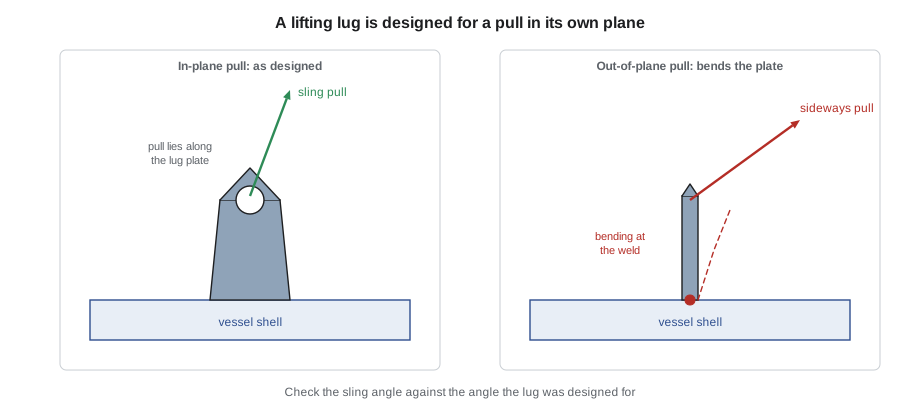
Lugs are strong in the direction they were designed for and weak in others. A lug plate loaded in its own plane, along the line of the plate, carries load well. Loaded sideways, across the plate, it bends and can tear out of its weld at a fraction of its in-plane capacity. That is why a lug is set so that the sling leg pulls in the plane of the plate, and why the angle of each sling leg must be checked against the angle the lug was designed for. A lug rated for a vertical pull may not be rated for a sling at 45 degrees.
Boilermakers often install the lifting attachments on site for equipment that arrives without them, or for removing old equipment. This is welding to an engineered design, not a judgement call. The lug's size, plate thickness, hole, weld size and location come from the lift engineer, the welding is done by a qualified welder to an approved procedure, and the welds are inspected, usually by magnetic particle or dye penetrant testing, before the lug is used. On a pressure vessel, the owner's inspector must approve any welding on the pressure boundary; many owners forbid it and require lugs on pads or on non-pressure parts such as skirts.
The design of below-the-hook lifting devices, including lifting beams, spreader bars and some lifting attachments, is covered by ASME BTH-1, and their marking, inspection and use by ASME B30.20. In Alberta, the Code's rigging rules require every lifting device to be designed to a standard and marked with its capacity.
Slings for heavy loads
The slings used on heavy lifts are the same types Kiera met in her core course, only bigger. Wire rope slings, from hand-spliced eyes to mechanically spliced, are the workhorses, with steel strength and good resistance to cutting. Grommets, endless loops made from a single strand of wire rope laid around itself, are used for very heavy loads because they are strong for their size and can be laid around trunnions. Synthetic roundslings, made from many loops of polyester or high-performance fibre inside a protective cover, are light, flexible and kind to the load's surface, and the largest can lift hundreds of tonnes; they must be protected from sharp edges and heat. Alloy chain slings are tough and resist heat and abrasion, and are common for rigging inside boilers and for moving hot or rough items.
| Sling type | Strengths | Watch for |
|---|---|---|
| Wire rope sling | Strong, resistant to cutting and heat, inexpensive | Kinks, broken wires, crushing, bending over small diameters |
| Wire rope grommet | Very high capacity for its size, good on trunnions | Bending ratio over pins and trunnions, core damage |
| Synthetic roundsling | Light, flexible, protects surfaces | Cuts at edges, heat, chemicals, hidden core damage |
| Alloy chain sling | Tough, heat-resistant, adjustable | Stretched or nicked links, wrong grade, weight of the chain |
Two details matter more with heavy slings than small ones. The first is the bending ratio: a wire rope sling or grommet bent around a pin, shackle or trunnion loses strength if the diameter it is bent around is small compared with the rope's own diameter. Sling makers publish efficiency tables for this, and trunnions are sized so that the sling's bend is gentle. The second is edge protection. A roundsling across the sharp edge of a skirt or a structural shape can be cut under load in an instant, so corner protectors, pads or softeners are used wherever a sling meets an edge.
Unequal sling legs
When a load's centre of gravity is not midway between its lifting points, the hook must be directly over the centre of gravity for the load to hang level. The two sling legs then have different lengths and different angles, and they carry different loads. The leg on the side nearer the centre of gravity is shorter, steeper and carries more of the weight. The shares come from moments: each leg's vertical share is proportional to the horizontal distance from the other leg's lug to the centre of gravity. The tension in each leg is its vertical share divided by the sine of its angle from the horizontal.
The reboiler shell's lugs are 6.0 m apart, and the fabricator's drawing puts the centre of gravity 2.6 m from lug 1 and 3.4 m from lug 2, because the shell's thicker head end is near lug 1. The crane's hook will be 4.0 m above the lugs.
# Unequal sling legs to a load whose CG is off centre (metric)
import math
W = 41_000                     # load weight (kg)
d1, d2 = 2.6, 3.4         # horizontal distance from the CG to lug 1 and lug 2 (m)
h = 4.0                     # height of the hook above the lugs (m)
# the hook must be directly over the CG; each leg runs from the hook to its lug
a1 = math.degrees(math.atan2(h, d1)); a2 = math.degrees(math.atan2(h, d2))
L1 = math.hypot(d1, h); L2 = math.hypot(d2, h)
# vertical shares from moments about the CG, then tension = vertical / sin(angle)
V1 = W * d2 / (d1 + d2); V2 = W * d1 / (d1 + d2)
T1 = V1 / math.sin(math.radians(a1)); T2 = V2 / math.sin(math.radians(a2))
print(f"leg 1: length {L1:5.2f} m, angle {a1:4.1f} deg from horizontal, vertical {V1:7,.0f}, tension {T1:7,.0f} kg")
print(f"leg 2: length {L2:5.2f} m, angle {a2:4.1f} deg from horizontal, vertical {V2:7,.0f}, tension {T2:7,.0f} kg")
# lug check: in-plane load on each lug and the sideways part
for n, T, a in ((1, T1, a1), (2, T2, a2)):
    side = T * math.cos(math.radians(a))
    print(f"lug {n}: resultant {T:7,.0f} kg at {90 - a:4.1f} deg from vertical, horizontal pull {side:7,.0f} kg")
print(f"choose slings and shackles rated for at least {max(T1, T2):,.0f} kg each")leg 1: length 4.77 m, angle 57.0 deg from horizontal, vertical 23,233, tension 27,710 kg leg 2: length 5.25 m, angle 49.6 deg from horizontal, vertical 17,767, tension 23,318 kg lug 1: resultant 27,710 kg at 33.0 deg from vertical, horizontal pull 15,102 kg lug 2: resultant 23,318 kg at 40.4 deg from vertical, horizontal pull 15,102 kg choose slings and shackles rated for at least 27,710 kg each
Lug 1, nearer the centre of gravity, carries 23.2 t of the weight vertically but, because its sling is at 57 degrees, its tension is 27.7 t, two-thirds of the whole shell's weight. Lug 2 carries 23.3 t of tension. A crew that chose slings for half the weight, 20.5 t, would overload the sling at lug 1 by over a third. The horizontal pull on the two lugs is the same, as it must be for the load to balance: each sling pulls the lug toward the hook with 15.1 t, and the lug must be designed for a pull at 33 or 40 degrees from vertical, not just straight up.
The slings could also be made the same length, with the hook moved toward the heavy end. That is not possible with a single hook and two slings: a single hook above two equal slings sits midway between the lugs, and the load would tilt until its centre of gravity was under it. Unequal lengths, a lifting beam with an adjustable hook point, or a chain hoist in one leg to fine-tune its length are the usual answers.
Shackles and hardware for heavy loads
Heavy shackles are bolt-type anchor or wide-body shackles, with a nut and a cotter pin so that the pin cannot unscrew under load. Wide-body shackles have a wide, curved bow that gives a large bearing surface for a wire rope or synthetic sling, improving the bending ratio. A shackle is rated for a load in line with its bow and pin; side loading reduces its capacity, and the maker's tables give the reduction. The pin goes through the lug and the sling sits in the bow, never the other way round, because a sling across a pin is bent too sharply and the pin can roll.
Kiera's job at the reboiler is to fit the shackles to the lugs. The lugs were made for 35 t shackles, and Dale shows her how to check that the pin fits the hole without excessive clearance, that the shackle's jaw fits over the lug plate with room for the plate but without slack, and that the pin is fully tightened and the cotter installed. A shackle too big for the lug sits crooked; a hole too big for the pin concentrates the load on one edge of the hole and can tear it.
Spreader bars and lifting beams
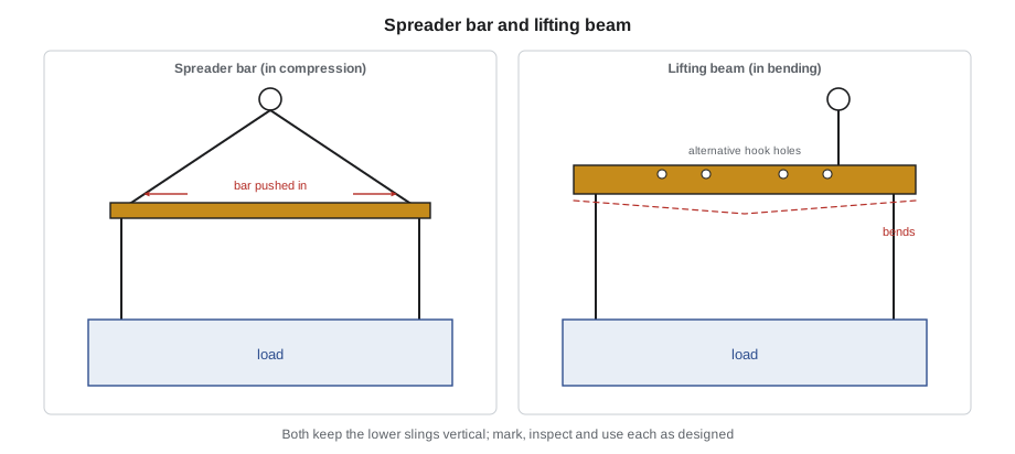
Many heavy lifts use a spreader bar or a lifting beam between the hook and the slings. A spreader bar is a strut held in compression between two sling legs that run up to the hook; it keeps the lower slings vertical, so they put no sideways load on the lugs and do not squeeze the load. A lifting beam is a beam that hangs from the hook and carries the load in bending, with its own lifting points along its underside. Lifting beams take up less headroom than a spreader bar arrangement, and many have several lifting holes so the hook point can be matched to an off-centre centre of gravity.
For the coker drum, the crane company supplies a lifting beam with a capacity of 400 t, designed for the drum's two top trunnions. Its two hooks carry grommets that wrap around the trunnions, and the beam keeps them vertical so that the trunnions take only vertical load during the main part of the lift. The beam weighs 8 t, and that weight, with the grommets and shackles, counts as part of the load on the crane.
A below-the-hook device must be marked with its rated load and its own weight, inspected before use and used only as designed. A spreader bar designed for vertical slings below must not be used with the lower slings at an angle, and a lifting beam must not be loaded at a point it was not designed for. If the device has no capacity marking, it is not used.
Rigging for the lift that follows
Riggers think ahead. A sling choice that works for the lift from the truck may not work for the set on the saddles, where the lower ends of the saddle bolts and the column next to it limit the space. The rigging must also come off. For the reboiler, the slings must be removable once the shell is resting on its saddles without anyone climbing on top of the shell under a suspended crane block. Dale chooses shackles with the pins on the outside, so that they can be removed from a man-lift once the shell is set and the load is off the slings.
Worked problem
Choosing slings for an off-centre load
An exchanger weighing 19 t has two lugs 7.0 m apart, with the centre of gravity 3.0 m from lug 1. The hook will be 3.5 m above the lugs. Find the vertical share and tension at lug 1.
Show solution
- Distance from lug 2 to the centre of gravity: 7.0 − 3.0 = 4.0 m.
- Vertical share at lug 1: 19 × 4.0 / 7.0 = 10.9 t.
- Angle of leg 1 from horizontal: arctan(3.5 / 3.0) = about 49 degrees.
- Tension in leg 1: 10.9 / sin 49° = 14.4 t.
Answer: Leg 1 needs a sling and shackle rated for at least 14.4 t, three-quarters of the exchanger's weight, not half.
Common mistakes
MistakeChoosing each sling for half the load weight.
InsteadCalculate each leg's tension from the centre of gravity and the sling angle.
MistakeLoading a lug across its plate.
InsteadAlign the shackle and sling with the plane of the lug; check the design angle.
MistakeWelding a lifting lug to a pressure vessel without approval.
InsteadLugs are engineered and their welds inspected; welding on a pressure boundary needs the owner's approval.
MistakePutting the sling over the shackle pin.
InsteadThe pin goes through the lug; the sling sits in the bow.
MistakeUsing a lifting beam with no capacity marking.
InsteadEvery below-the-hook device must be marked with its rated load and weight.
Summary and key terms
- Lugs, trunnions and tailing lugs are engineered for a load in a particular direction; out-of-plane loads reduce their capacity.
- Lugs added on site follow the engineer's design, an approved welding procedure and inspection.
- Heavy lifts use wire rope slings, grommets, roundslings and chain slings, with attention to bending ratio and edge protection.
- With an off-centre centre of gravity, the sling nearer the centre of gravity is shorter, steeper and carries more load.
- Shackle pins go through the lug, the sling sits in the bow, and side loading reduces the rating.
- Spreader bars and lifting beams keep slings vertical; they must be marked, inspected and used as designed.
- Lifting lug
- A plate welded to a load with a hole for a shackle pin, designed for lifting.
- Trunnion
- A stub welded to a vessel around which a sling is placed, allowing the vessel to rotate during upending.
- Tailing lug
- A lug at the bottom of a vertical vessel used by the tail crane during upending.
- Grommet
- An endless wire rope sling made from a single strand laid around itself.
- Spreader bar
- A strut held in compression between sling legs to keep the lower slings vertical.
- Lifting beam
- A beam that hangs from the hook and carries the load in bending.
- Bending ratio
- The diameter a sling is bent around divided by the sling diameter.
Practice problems
Work each problem on paper first, then reveal the answer to check.
A 30 t load hangs from two lugs 5 m apart with its centre of gravity 2 m from lug 1. What vertical load does lug 1 carry?
Show answer
30 × 3 / 5 = 18 t.
If that sling is at 60 degrees from horizontal, what is its tension?
Show answer
18 / sin 60° = 20.8 t.
Why are trunnions used instead of lugs at the top of a vessel that will be upended?
Show answer
The sling can rotate around the trunnion as the vessel turns from horizontal to vertical.
What is the difference between a spreader bar and a lifting beam?
Show answer
A spreader bar is in compression between sling legs; a lifting beam carries the load in bending.
Lesson quiz · 5 questions
Score 60% or more to complete this lesson.
Create a free account to save your progress, take quizzes and earn a certificate.