
BLR-120 · Lesson 2 of 12 · 20 min
Load weight and centre of gravity of vessels and components
Every lift plan begins with two numbers: how much the load weighs and where its centre of gravity is. Get either one wrong and everything that follows, from the choice of crane to the length of the slings, is built on a mistake. For the small loads in Kiera's core course, the weight came from a tag, a catalogue or a quick calculation. The loads on the Northgate turnaround are different. A coker drum, a reboiler shell or an exchanger bundle is a one-off item with a weight that depends on plate thickness, nozzles, internals, insulation and whatever the process has left inside it. This lesson shows how a boilermaker builds up a vessel's weight and finds its centre of gravity, and how to judge how far those numbers can be trusted.
Where weights come from
The best weight is a measured one. Some loads can be weighed directly: a vessel lifted at the fabricator's shop with a crane fitted with a load indicator, or a component weighed on a truck scale on the way to site. Many fabricators weigh large vessels before shipping and record the weight on the shipping documents. The next best source is the fabricator's weight calculation, which adds up every plate, nozzle and attachment from the shop drawings. After that come the vessel's general arrangement drawing, which usually states an empty weight, an operating weight and a test weight, and the nameplate, which on a pressure vessel may or may not give a weight.
For old equipment being removed, the weight is harder to know. The original drawings may be lost or out of date; the equipment may have been repaired, re-trayed or modified; and it will almost certainly contain something the drawing does not show. A coker drum that has been in service for twenty years has thinner walls in some places from corrosion, thicker ones in others from weld overlay repairs, and may carry several tonnes of coke stuck to its walls even after it has been cut out and steamed. An exchanger bundle may hold sludge and scale; a boiler tube panel may be full of water or ash. Dale's rule for removed equipment is simple: treat the drawing weight as a minimum, look inside if you can, and add a contingency that matches how little you know.
| Source | Confidence | Typical contingency used |
|---|---|---|
| Weighed on a calibrated scale or load cell | High | 0 to 3 percent |
| Fabricator's detailed weight calculation | Good | 3 to 5 percent |
| General arrangement drawing weight | Fair | 5 to 10 percent |
| Estimated from dimensions by the crew | Fair to poor | 10 percent or more, and a trial lift |
| Old equipment with residue or unknown repairs | Poor | 10 to 20 percent, inspection inside, trial lift with a load cell |
Contingency is not a fudge factor to make a lift look comfortable; it is an honest statement of uncertainty. The crane and the rigging must be chosen for the contingency weight, not the best guess.
Building up a vessel's weight
When no reliable weight is available, the crew builds one from the drawings, piece by piece, the same way the fabricator would. Each part of the vessel is a simple shape whose weight is its volume of steel multiplied by the density of steel, 7,850 kg/m³, or 7.85 t/m³.
For a cylindrical shell, the steel volume is the circumference times the length times the wall thickness, using the mean diameter for accuracy or the outside diameter for a slightly conservative answer. Heads are harder. A 2:1 ellipsoidal head, the most common shape on pressure vessels, has a surface area of about 1.084 times the square of the diameter; a hemispherical head has an area of half a sphere; cones and flat heads follow from their geometry. Nozzles, manways, flanges, skirts, saddles, internal trays, baffles, platforms clips and lifting lugs are added from the drawing or the fabricator's list, and refractory or insulation, if installed, is added by its own density.
| Material | Approximate density |
|---|---|
| Carbon and low-alloy steel | 7,850 kg/m³ |
| Stainless steel | 7,900 to 8,000 kg/m³ |
| Water | 1,000 kg/m³ |
| Dense castable refractory | 2,000 to 2,400 kg/m³ |
| Insulating castable | 500 to 1,200 kg/m³ |
| Petroleum coke, loose | 700 to 900 kg/m³ |
Centre of gravity
The centre of gravity is the point where the whole weight of the load can be considered to act. A freely suspended load always hangs with its centre of gravity directly below the hook. If the hook is not above the centre of gravity when the load leaves the ground, the load will swing or tilt until it is, and in doing so it changes the loads in the slings, may strike something and can shift the crane's radius. For a symmetrical object of uniform material the centre of gravity is at its geometric centre. For a vessel with a heavy cone at one end, thick nozzles at the other, and a skirt, it is somewhere else, and has to be calculated.
The calculation uses moments. Each part's weight is multiplied by the distance from a reference point, such as the base of the skirt, to that part's own centre of gravity; the moments are added; and the total moment is divided by the total weight.
For a vertical vessel, the useful distance is the height above the base, because it decides where the trunnions and tailing lug must be and how the load shares between the main crane and the tail crane. For a horizontal vessel or an exchanger, the useful distances are along its length and across it, because they decide where the hook must be and how long each sling must be.
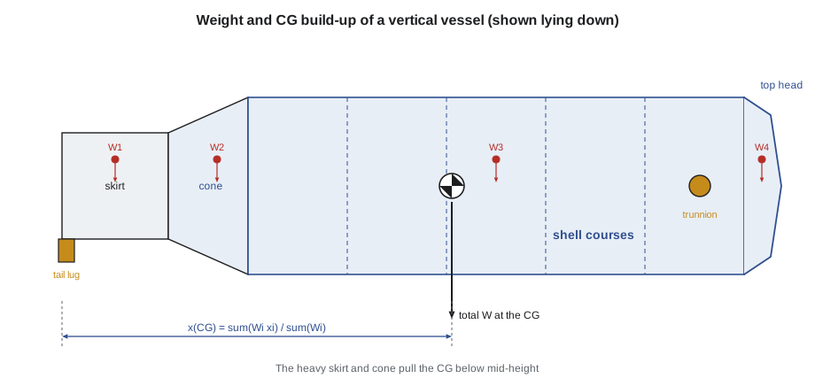
The Northgate coker drum
The new coker drum has been fabricated in sections, joined at the fabricator's yard and shipped to Northgate by road in one piece, arriving on a multi-axle trailer. The fabricator's weight report is on its way, but Wade wants his own check before the lift engineer finalizes the plan. He gives Kiera the general arrangement drawing and asks her to build up the weight and centre of gravity. The drum is 8.5 m in diameter, with a shell 27 m long, a bottom cone 5.5 m deep to the skirt, a 2:1 ellipsoidal top head and a skirt 6 m tall. Its average wall is 32 mm and the skirt is 25 mm. The drawing lists nozzles, clips, the lifting trunnions and the tail lug at about 18 t, and the top platform steel that will be pre-dressed on the drum before the lift at about 9 t.
# Weight and centre of gravity of the new coker drum (metric, illustrative)
import math
rho = 7.85                 # steel density
D, t = 8.5, 0.032             # shell outside diameter and average wall thickness
parts = []                  # (name, weight, height of its own CG above the skirt base)
skirt_h, cone_h, shell_h = 6.0, 5.5, 27.0
shell = math.pi * D * shell_h * t * rho
parts.append(("shell courses", shell, skirt_h + cone_h + shell_h / 2))
head = 1.084 * D ** 2 * t * rho                  # 2:1 ellipsoidal head, surface area 1.084 D^2
parts.append(("top head", head, skirt_h + cone_h + shell_h + D / 8))
cone = math.pi * (D / 2) * math.hypot(D / 2, cone_h) * t * 1.25 * rho   # thicker bottom cone
parts.append(("bottom cone", cone, skirt_h + cone_h * 2 / 3))
skirt = math.pi * D * skirt_h * 0.025 * rho
parts.append(("skirt", skirt, skirt_h / 2))
parts.append(("nozzles, clips, trunnions", 18.0, skirt_h + cone_h + shell_h * 0.8))
parts.append(("platform steel (pre-dressed)", 9.0, skirt_h + cone_h + shell_h + 1.0 * 1))
total = sum(w for _, w, _ in parts)
cg = sum(w * h for _, w, h in parts) / total
for name, w, h in parts:
    print(f"{name:<30} {w:9,.1f} t   CG at {h:5.1f} m")
print(f"{'total':<30} {total:9,.1f} t")
print(f"overall height {skirt_h + cone_h + shell_h + D / 4:.1f} m, centre of gravity {cg:.1f} m above the skirt base")
print(f"with a 3 % weight contingency for the lift plan: {total * 1.03:,.1f} t")shell courses 181.1 t CG at 25.0 m top head 19.7 t CG at 39.6 m bottom cone 29.1 t CG at 9.7 m skirt 31.4 t CG at 3.0 m nozzles, clips, trunnions 18.0 t CG at 33.1 m platform steel (pre-dressed) 9.0 t CG at 39.5 m total 288.4 t overall height 40.6 m, centre of gravity 23.0 m above the skirt base with a 3 % weight contingency for the lift plan: 297.0 t
Kiera's build-up gives 288.4 t, against the fabricator's figure, when it arrives, of 291 t. The difference is under 1 percent, which gives Wade confidence in both numbers. The lift plan uses the fabricator's weight plus a 3 percent contingency, because the drum is new and its records are good. The centre of gravity sits about 23 m above the skirt base, a little below mid-height, because the skirt and the thick bottom cone are heavy, even though the platform steel and nozzles add weight near the top.
The same build-up is done for the old drum, which comes out first, and there the answer is less certain. The old drum's walls have been weld overlaid in several areas over the years, and the inspector believes that a layer of hard coke remains on the upper walls after decoking. Wade adds a 15 percent contingency to the old drum's weight and plans a trial lift with a load cell under the main hook before the old drum is fully freed.
Contents, residues and things that move
Loads that contain liquids or loose solids have a second problem: the centre of gravity can move during the lift. A vessel partly full of water will slosh when tilted, shifting its weight toward the low end and suddenly loading one sling more than the other. Coke, catalyst, sand or ash can slide. Even a bundle of tubes can shift inside a frame. The only good answer is to empty and clean the load before lifting it, and to confirm it is empty: open the drains, look inside, weigh it if possible. Where a load cannot be emptied completely, the lift plan treats the contents as a moving weight and checks the worst position.
Equipment removed from a plant may also hold residual hydrocarbons, hydrogen sulphide or pyrophoric scale. These are not just a weight problem; they are a hazard to the riggers who attach the slings and a fire hazard if cutting is planned nearby. The owner's decontamination and gas testing must be complete before the rigging crew approaches, and the hazards from the first course apply here as much as in a confined space.
Checking the centre of gravity on the hook
However good the calculation, the first few centimetres of a lift tell the truth. A trial lift, sometimes called a test pick, raises the load just clear of its supports and holds it. The crew watches for tilt, for one sling tightening before another, for the crane's load indicator reading more than the plan, and for anything that moves inside the load. If the load tilts, the hook is not over the centre of gravity. The load is set back down, the rigging adjusted, and the trial repeated. Lifting a tilting load higher in the hope it will settle is how slings are overloaded and loads are dropped.
Kiera will see this on the old drum. The trial lift shows a load cell reading 6 percent over the drawing weight, inside the contingency, and a slight tilt toward the bottom. Dale and Wade adjust the tail rigging, try again, and the drum hangs level.
Worked problem
Finding the centre of gravity of an exchanger
An exchanger lies horizontally, 9.0 m long. Its shell and tubes weigh 14 t with their centre at mid-length, the channel head at the left end weighs 3.5 t with its centre 0.6 m from the left end, and the floating head cover at the right end weighs 1.5 t with its centre 0.4 m from the right end. Where is the centre of gravity?
Show solution
- Measure from the left end. Shell and tubes: 14 × 4.5 = 63.0 t·m.
- Channel head: 3.5 × 0.6 = 2.1 t·m.
- Floating head cover: 1.5 × 8.6 = 12.9 t·m.
- Total weight 19.0 t; total moment 78.0 t·m.
- Centre of gravity: 78.0 / 19.0 = 4.1 m from the left end.
Answer: The centre of gravity is about 0.4 m left of mid-length, toward the heavy channel head. The hook must be over that point, so the slings will not be the same length.
Common mistakes
MistakeUsing the drawing weight for old equipment without allowing for residue, overlay and repairs.
InsteadTreat the drawing weight as a minimum; inspect, add contingency and weigh during a trial lift.
MistakeAssuming the centre of gravity is at the middle.
InsteadCalculate it from the parts; heavy heads, cones and skirts move it.
MistakeLifting a load that tilts in the trial lift.
InsteadSet it down and adjust the rigging until it hangs as planned.
MistakeLifting a vessel with water or loose solids inside.
InsteadDrain, clean and confirm it is empty, or plan for the moving weight.
MistakeChoosing the crane for the best-guess weight.
InsteadChoose the crane and rigging for the weight with contingency.
Summary and key terms
- The best weight is measured; next come the fabricator's calculation, the drawing and the crew's own estimate.
- Old equipment usually weighs more than its drawing because of residue, overlay, repairs and contents.
- A weight build-up adds the steel in each part at 7.85 t/m³ plus nozzles, internals, refractory and attachments.
- The centre of gravity is the weighted average of the parts' centres, found by adding moments and dividing by the total weight.
- A suspended load hangs with its centre of gravity under the hook; if the hook is not there, the load tilts or swings.
- A trial lift checks the weight and centre of gravity before the load is committed.
- Centre of gravity
- The point at which the whole weight of an object can be considered to act.
- Contingency
- An allowance added to an estimated weight to cover uncertainty.
- Weight build-up
- An estimate of a load's weight made by adding the weights of its parts.
- Trial lift
- Lifting a load just clear of its supports to check its weight, balance and rigging before the full lift.
- Moment
- A weight multiplied by its distance from a reference point.
- Load cell
- A calibrated device placed in the rigging that measures the load directly.
Practice problems
Work each problem on paper first, then reveal the answer to check.
What is the steel weight of a cylindrical shell 3.0 m in diameter, 10 m long and 20 mm thick?
Show answer
π × 3.0 × 10 × 0.020 × 7.85 = 14.8 t.
A load is made of a 10 t part with its centre 2 m from a reference point and a 5 t part with its centre 8 m away. Where is the centre of gravity?
Show answer
(10 × 2 + 5 × 8) / 15 = 4.0 m from the reference point.
Why does an old coker drum weigh more than its drawing?
Show answer
Weld overlay repairs, remaining coke and other residues, and attachments added over the years.
What should the crew do if the load tilts in the trial lift?
Show answer
Set it down and adjust the rigging so the hook is over the centre of gravity.
Lesson quiz · 5 questions
Score 60% or more to complete this lesson.
Create a free account to save your progress, take quizzes and earn a certificate.