
AUTO-410 · Lesson 3 of 12 · 20 min
De-energizing and verifying zero energy
Dr. Singh's hatchback comes in with a pink crust on a coolant fitting at the rear drive unit, where the inverter's cooling loop joins the motor housing. The fitting is cheap. Reaching it is not: the orange cable from the battery to the rear inverter runs directly over it and has to be unbolted and moved aside. Marty reads the service information, then turns to Kiran. "This is your first high-voltage job. I'm the qualified person, Dale is the observer, and you'll do every step with me watching. Nothing happens until we've proven the system is dead."
This lesson follows that job through the procedure every high-voltage technician uses: preparing the vehicle, disabling the high-voltage system, locking it out, waiting for stored energy to discharge, and verifying the absence of voltage with a rated meter. It then covers working on the de-energized system and bringing it back into service.
Why the maker's procedure comes first
Every electrified vehicle can be made safe, but no two are made safe in exactly the same way. The service disconnect may be a plug under the rear seat, a lever under the floor, a fuse in the battery or a pyrotechnic switch. Some vehicles require the 12 volt battery to be disconnected first and some last. Wait times range from a few minutes to more than ten. The test points for verifying zero voltage are at different connectors on different models. So the first step of every job is the service information for that vehicle, year and model, printed or open beside the bay, and followed step by step.
The general principles are the same everywhere, and they come from the electrical safety standards. A system is in an electrically safe work condition only when it has been disconnected from every energy source, locked out, tested and found to have no voltage, and protected from being turned back on. Until all those things are true, the system is treated as live and worked on only with full shock protection.
Step 1: prepare the vehicle and the bay
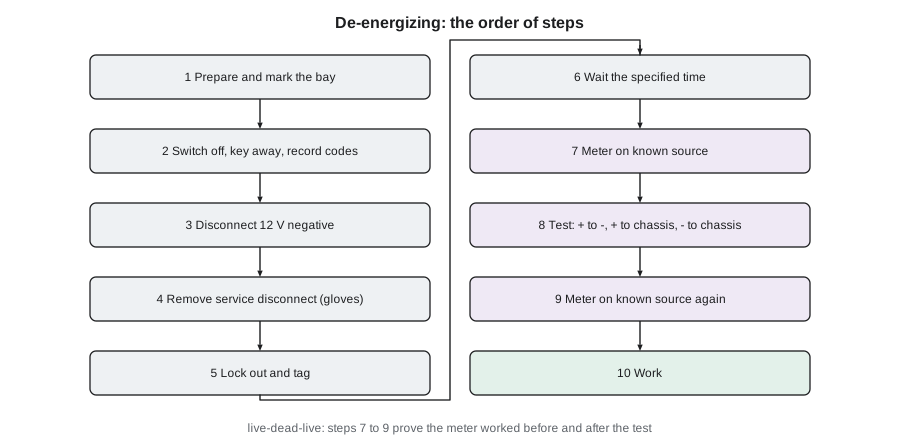
Kiran parks the hatchback in the high-voltage bay and Dale tapes the barrier around it. She switches the vehicle off and checks that the ready indicator is out. On an electric vehicle, "off" is a state the modules choose, not a key position, so she confirms it on the instrument cluster and on the scan tool. The smart key goes into the shielded box on the bench, more than 5 m (more than 16 ft) away, so the vehicle cannot detect it and wake. She records the battery's state of charge and any diagnostic trouble codes before anything is disconnected, so that the vehicle's condition before the work is documented.
Marty inspects the PPE with her: class 0 gloves air-tested and within their retest date, leather protectors, face shield, insulated tools laid out on an insulating mat. Dale checks the CAT III meter on the shop's known live source, a small test box that produces a steady voltage, so that the meter is proven to work before it is trusted to read zero.
Step 2: disable the high-voltage system
The maker's procedure for this hatchback has three parts. First, the 12 volt battery's negative cable is disconnected, which stops the modules from commanding the contactors closed. Second, a wait of one minute lets the modules shut down. Third, with gloves on, Marty removes the service disconnect, a plug with an interlock loop that sits in a hatch under the rear seat. Removing it opens the battery's internal circuit in the middle of the pack and breaks the interlock circuit, so the contactors cannot close even if the 12 volt system is reconnected by mistake.
With the service disconnect out, the pack's two halves are separated, but the pack itself is never de-energized: its cells still hold their charge. What has been made safe is everything outside the pack: the cables, the inverter, the motor and the accessories. The pack's own terminals and internal busbars remain live, and only specialists open a traction battery, in a battery repair area, following the maker's procedure.
Step 3: lock out and tag out
Once the service disconnect is out, it cannot be left on the bench where someone might put it back. Marty puts it in his pocket, then fits a lockout cover over the empty socket with his personal padlock and a tag with his name, the date and the reason. The 12 volt negative cable gets a cable cover and its own tag. Alberta's OHS Code, Part 15, requires hazardous energy to be isolated and secured with a personal lock before work, and CSA Z460 describes the methods. (OSHA's lockout/tagout standard, 1910.147, and the electrical work practices in 1910.333 require energy sources to be isolated and secured with a personal lock and tag before work.) Each person who works on the vehicle adds a lock, and only the person who placed a lock removes it.
Step 4: wait for stored energy to discharge
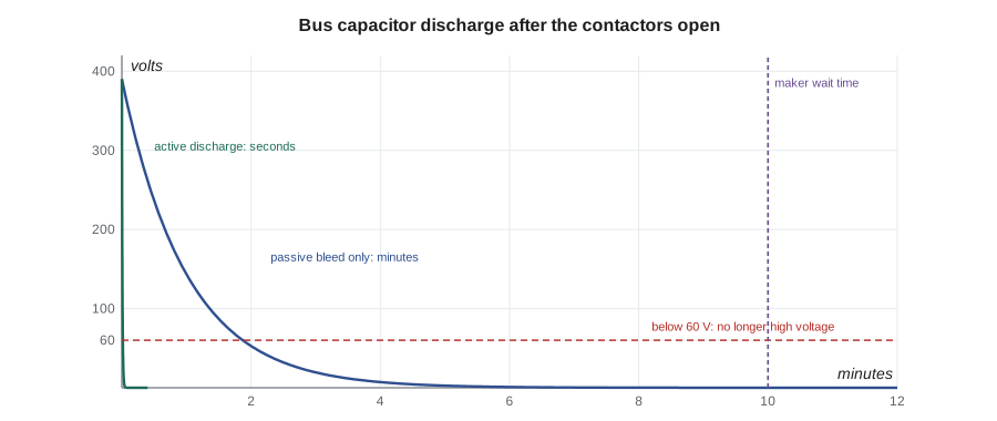
The inverter, the DC-DC converter and the onboard charger contain large capacitors that smooth the DC bus voltage. When the pack is disconnected, these capacitors still hold a charge, and they can deliver a dangerous shock. Most systems include an active discharge circuit that drains them within a few seconds when the contactors open, plus passive bleed resistors that drain them more slowly if the active circuit fails. The maker's wait time, ten minutes on this hatchback, allows for the slow case.
The capacitor's voltage falls exponentially. The time constant, the product of the resistance and the capacitance, is the time to fall to about 37 percent of the starting voltage. After five time constants, less than 1 percent remains.
# How long the inverter's DC bus capacitor takes to bleed down through its passive resistor
import math
v0 = 390.0          # bus voltage when the contactors opened
c = 800e-6          # bus capacitance, farads (800 microfarads)
r = 75e3            # passive bleed resistance, ohms
v_safe = 60.0       # below the high-voltage threshold
tau = r * c
t_safe = tau * math.log(v0 / v_safe)
print(f"time constant {tau:.0f} s; below {v_safe:.0f} V after {t_safe:.0f} s ({t_safe / 60:.1f} min)")
for t in (0, 30, 60, 120, 180, 300, 600):
print(f" after {t:3} s: {v0 * math.exp(-t / tau):6.1f} V")time constant 60 s; below 60 V after 112 s (1.9 min) after 0 s: 390.0 V after 30 s: 236.5 V after 60 s: 143.5 V after 120 s: 52.8 V after 180 s: 19.4 V after 300 s: 2.6 V after 600 s: 0.0 V
With the active discharge circuit working, the bus falls below 60 volts in a second or two. With it failed, the passive resistor alone takes almost two minutes. The maker's ten-minute wait covers that case with a margin, and it is why nobody shortens a wait time, even when the meter seems to promise a quicker result.
Step 5: verify the absence of voltage
The wait time is not proof. The proof is a measurement, made with a CAT III meter, gloves on, at the points the service information specifies, after the wait. On the hatchback, the test point is the rear inverter's DC input connector once its cover is removed. The test follows the live-dead-live method: test the meter on the known live source, test the circuit, then test the meter on the known source again. If the meter failed between the two checks, a dangerous circuit could read zero, so the second check is not optional.
At the circuit, three measurements are taken: positive to negative, positive to the vehicle chassis and negative to the vehicle chassis. The last two catch a fault in which one side of the high-voltage system has leaked to the body, which would make the body itself live relative to the other side. All three must read below the threshold given by the maker, typically less than a few volts. Kiran holds the probes and reads each value aloud; Marty records them on the job card.
# Verifying zero voltage: live-dead-live with three measurements at the test point
known_source = 24.0
before = 24.1          # meter reading on the known source before the test
after = 24.0            # and after
readings = {"positive to negative": 0.3, "positive to chassis": 0.1, "negative to chassis": 0.2}
limit = 3.0                # maker's limit for "no voltage present", volts
meter_ok = abs(before - known_source) < 2 and abs(after - known_source) < 2
print(f"meter check before: {before} V, after: {after} V -> {'meter working' if meter_ok else 'METER FAULT: test invalid'}")
for name, v in readings.items():
    print(f"  {name:20}: {v:5.1f} V {'ok' if abs(v) < limit else '<- VOLTAGE PRESENT: stop'}")
safe = meter_ok and all(abs(v) < limit for v in readings.values())
print("electrically safe work condition confirmed" if safe else "NOT SAFE: treat as live")meter check before: 24.1 V, after: 24.0 V -> meter working positive to negative: 0.3 V ok positive to chassis : 0.1 V ok negative to chassis : 0.2 V ok electrically safe work condition confirmed
Only now is the system in an electrically safe work condition. Marty signs the job card's verification line. Kiran unbolts the orange cable with an insulated wrench, caps its terminal with the insulating cover from the kit, moves it aside, replaces the coolant fitting and refills and bleeds the drive unit's loop with the scan tool's pump routine.
| Measurement | What a voltage would mean |
|---|---|
| Positive to negative | The bus is still charged: the pack is connected or the capacitors have not discharged |
| Positive to chassis | The negative side is leaking to the body, or the pack is connected |
| Negative to chassis | The positive side is leaking to the body, or the pack is connected |
Working on the de-energized system
Even with zero voltage verified, the pack itself remains live and its connectors must not be touched. Disconnected orange connectors are covered or taped so nothing can enter them. Tools are counted before and after, because a forgotten wrench inside a drive unit cover is a short circuit waiting for re-energizing. If the work is interrupted, for lunch or a parts delay, the locks stay on and the bay stays marked. If anyone leaves the job and someone else takes over, the new person verifies zero voltage again before touching anything.
Some jobs on electrified vehicles do not require de-energizing at all: tires, brakes, suspension, cabin filters and most 12 volt work. The service information says which jobs need it. A job that does not open any high-voltage component can be done with the system intact, as long as nobody disturbs an orange cable or connector.
Re-energizing and return to service
Bringing the system back is the procedure in reverse, with checks of its own. Kiran torques the orange cable's terminals to specification with an insulated torque wrench and refits every cover, because the covers are part of the interlock circuit on many vehicles and the system will not enable with one missing. Marty checks the tool count. If the maker specifies an insulation test after reconnecting a high-voltage component, it is done now; Kiran will learn that test in the diagnosis lesson. Then the bay is cleared of loose tools, Marty removes his lock, refits the service disconnect with gloves on, and reconnects the 12 volt battery.
With everyone clear, Kiran switches the vehicle on. The ready indicator comes on without warnings, the scan tool shows no new codes, and the battery management system reports normal isolation resistance. A road test confirms the drive unit runs quietly and the coolant level holds. The job card records each step, each measurement, the time of each lock and who did what, so that the work can be traced if anything is questioned later.
Worked problem
Planning the wait
An inverter's bus capacitor is 1,200 microfarads with a 47 kilohm passive bleed resistor. Starting at 400 volts, how long does it take to fall below 60 volts with only the passive resistor?
Show solution
- The time constant is 47,000 × 0.0012 = 56.4 seconds.
- The ratio is 400 ÷ 60 = 6.67, and ln 6.67 = 1.90.
- The time is 56.4 × 1.90 = 107 seconds, about 1.8 minutes.
Answer: About 1.8 minutes; the maker's wait time still applies, and the meter, not the calculation, proves the result.
Common mistakes
MistakeTrusting the wait time without measuring.
InsteadVerify zero voltage with a rated meter at the specified points.
MistakeTesting only positive to negative.
InsteadAlso test each side to chassis to catch an isolation fault.
MistakeSkipping the second meter check.
InsteadLive-dead-live: test the meter on a known source before and after.
MistakeLeaving the service disconnect on the bench.
InsteadKeep it in your pocket and lock out the socket.
MistakeAssuming the pack is dead once the disconnect is out.
InsteadOnly the circuits outside the pack are de-energized; the cells still hold their charge.
Summary and key terms
- The maker's procedure for the specific vehicle sets the order, the disconnect location, the wait time and the test points.
- Prepare the bay, switch off, move the key away and record codes before disconnecting anything.
- Disconnect the 12 volt system and remove the service disconnect with gloves, then lock and tag it.
- Wait the full specified time for capacitors to discharge.
- Verify zero voltage live-dead-live: positive to negative, and each side to chassis.
- The pack's cells stay charged; only the circuits outside it are made safe.
- Re-energize in reverse, with torque, covers, tool count and the maker's checks, and document every step.
- Electrically safe work condition
- A circuit disconnected, locked out, tested and found to have no voltage.
- Service disconnect
- A plug or switch that breaks the traction battery circuit for service.
- Interlock
- A low-voltage loop that prevents the contactors from closing when a cover or plug is removed.
- Lockout
- Securing an energy-isolating device with a personal lock so it cannot be restored.
- Time constant
- The product of resistance and capacitance; the time for a capacitor to fall to about 37 percent.
- Live-dead-live
- Testing a meter on a known source before and after checking a circuit for voltage.
Practice problems
Work each problem on paper first, then reveal the answer to check.
Why is the meter tested on a known source after the circuit test too?
Show answer
To prove it did not fail during the test and give a false zero.
What three measurements verify zero voltage?
Show answer
Positive to negative, positive to chassis and negative to chassis.
Why can't the wait time be shortened when the active discharge works?
Show answer
The wait covers the case where it has failed and only the bleed resistor drains the capacitors.
Who may remove a lockout padlock?
Show answer
Only the person who placed it.
Lesson quiz · 5 questions
Score 60% or more to complete this lesson.
Create a free account to save your progress, take quizzes and earn a certificate.