
AUTO-410 · Lesson 10 of 12 · 20 min
Charging: Level 1, Level 2 and DC fast charging
Hal Osei's trial year with the electric van is going well enough that he wants a plan for the whole fleet. He sits in Ridgeline's office with Bev, Marty and Kiran and lays out his questions. How long will a van take to charge overnight at the depot? How many chargers does he need, and how big an electrical service? What happens on the day a van comes back nearly empty and has to go out again at noon? And will his new vans use the same plug as the trial van? Bev turns to Kiran. "You've been reading the charging data from that van all year. Walk him through it."
This lesson explains how electrified vehicles charge: the three levels of charging, the connectors used in North America, how the vehicle and the station communicate, why charging slows as the battery fills, how to estimate charging time and cost, and how to diagnose a vehicle that will not charge. Installing charging stations is electricians' work, but technicians must understand the whole system to diagnose it and to advise customers.
The three levels
Level 1 charging uses an ordinary 120 volt household outlet through the portable cord set that comes with most vehicles. It delivers about 1.4 to 1.9 kilowatts, adding perhaps 8 to 12 km (5 to 8 miles) of range per hour. That is enough for a plug-in hybrid or a short daily commute, but slow for a large battery, and it is slower still in a cold garage, because some of the power goes to keeping the battery warm.
Level 2 charging uses a 208 or 240 volt circuit and a dedicated station, properly called electric vehicle supply equipment, or EVSE, wall-mounted at a home or business, or a public post. It typically delivers 7 to 11 kilowatts, limited by the station's rating, the circuit and the vehicle's onboard charger, whichever is lowest, and can reach 19.2 kilowatts on an 80 ampere circuit. It fills most electric vehicles overnight. In both Level 1 and Level 2 charging, the station supplies AC and the vehicle's onboard charger converts it to DC; the station itself is essentially a smart, protected switch.
DC fast charging, sometimes called Level 3, uses a large charger with its own AC-to-DC converter, connected to a three-phase commercial supply. It delivers DC straight to the battery through the vehicle's charging contactors, bypassing the onboard charger, at 50 to 350 kilowatts depending on the station and what the vehicle can accept. A compatible vehicle can go from about 10 to 80 percent in 20 to 40 minutes on a warm battery.
| Level | Supply | Typical power | Converter |
|---|---|---|---|
| Level 1 | 120 V AC household outlet | 1.4 to 1.9 kW | Vehicle's onboard charger |
| Level 2 | 208 or 240 V AC dedicated circuit | 7 to 19.2 kW | Vehicle's onboard charger |
| DC fast charging | Three-phase commercial supply | 50 to 350 kW | In the station |
Connectors
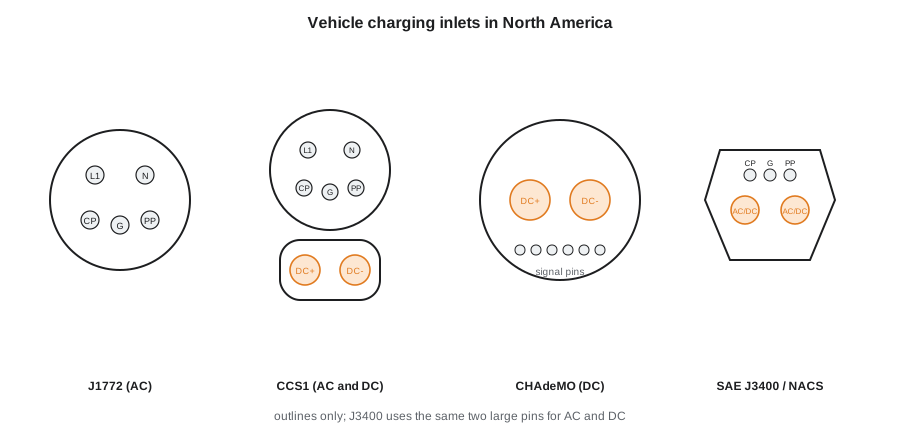
North America has used several connectors. For AC, most vehicles until recently used the SAE J1772 connector. For DC fast charging, most used the Combined Charging System, CCS1, which adds two large DC pins below a J1772 inlet; a few older models use the Japanese CHAdeMO connector. Tesla used its own compact connector for both AC and DC. In 2023, SAE began standardizing that connector as SAE J3400, also known as the North American Charging Standard or NACS, and nearly every maker selling in Canada and the United States has announced that it will switch to J3400 inlets, with many 2025 and 2026 models already built with them and older vehicles using adapters. For years to come, technicians will see all of these on the road, and the charging network will offer more than one connector.
Hal's trial van has a CCS1 inlet; the vans he would order next year are listed with J3400 inlets. Kiran tells him what that means in practice: his depot stations should either have J3400 connectors or the van maker's approved adapters, and adapters must be the maker's approved ones, rated for the current, because a poor adapter can overheat. She also tells him the public networks in Alberta (Colorado) now offer both connectors at many sites.
How the vehicle and station communicate
Before any power flows, the vehicle and the station must agree. For AC charging, they talk over the control pilot circuit, a pin that carries a 1 kilohertz square wave from the station. The vehicle signals its state by switching resistors onto the pilot line, which changes the voltage the station measures: connected, ready to charge, or charging with ventilation required. The station tells the vehicle the maximum current it may draw by the duty cycle of the square wave. A second signal, the proximity pin, tells the vehicle a connector is inserted and, on J1772, when the release button is pressed, so the vehicle can stop the current before the connector is pulled.
For DC fast charging, the vehicle and station exchange much more information, including the battery's voltage, its current limits and its temperature, over a digital link. On CCS and J3400 vehicles, that link uses power line communication over the control pilot. The ISO 15118 standard adds features such as Plug and Charge, in which the vehicle identifies itself and pays automatically.
# Control pilot: the station's duty cycle tells the vehicle the maximum AC current it may draw (SAE J1772)
def max_amps(duty_percent):
    if duty_percent < 8: return 0.0                  # charging not allowed
    if duty_percent < 10: return 6.0
    if duty_percent <= 85: return duty_percent * 0.6
    if duty_percent <= 96: return (duty_percent - 64) * 2.5
    return 0.0
for d in (10, 16, 25, 40, 53.3, 66.7, 90, 96):
    a = max_amps(d)
print(f"duty {d:5.1f} percent -> up to {a:5.1f} A, about {a * 240 / 1000:5.1f} kW at 240 V")duty 10.0 percent -> up to 6.0 A, about 1.4 kW at 240 V duty 16.0 percent -> up to 9.6 A, about 2.3 kW at 240 V duty 25.0 percent -> up to 15.0 A, about 3.6 kW at 240 V duty 40.0 percent -> up to 24.0 A, about 5.8 kW at 240 V duty 53.3 percent -> up to 32.0 A, about 7.7 kW at 240 V duty 66.7 percent -> up to 40.0 A, about 9.6 kW at 240 V duty 90.0 percent -> up to 65.0 A, about 15.6 kW at 240 V duty 96.0 percent -> up to 80.0 A, about 19.2 kW at 240 V
| Pilot voltage seen by the station | Vehicle state |
|---|---|
| +12 V | Not connected |
| +9 V | Connected, not ready |
| +6 V | Ready, charging |
| +3 V | Charging, ventilation required (rare) |
| 0 V or −12 V | Fault or no pilot |
Why charging slows down
A lithium-ion battery charges in two phases. In the first, constant current, the charger pushes as much current as the battery will accept, and the voltage rises. When the cell voltage approaches its maximum, the charger switches to constant voltage, holding the voltage steady while the current tapers off. DC fast charging follows the same pattern on a large scale: power stays high from a low state of charge to somewhere around 50 to 60 percent, then falls steadily, and the last 20 percent can take as long as the first 70. That is why the usual advice is to fast-charge to about 80 percent and continue the trip.
Temperature matters as much as state of charge. A cold battery accepts only a small fraction of its rated charging power, because charging cold cells quickly can plate lithium. Vehicles with battery preconditioning warm the pack while driving to a fast charger if the driver selects the charger in the navigation system. Hal's drivers will learn this the hard way in January if nobody tells them.
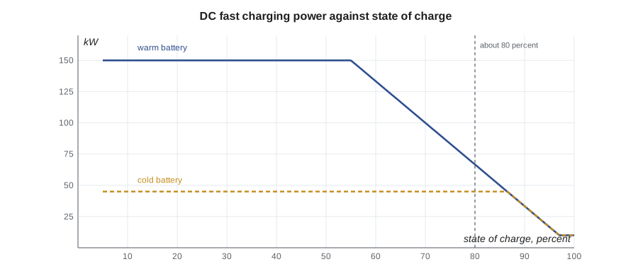
# Charging time estimate: Level 2 overnight and DC fast charging with the taper (illustrative curve)
pack_kwh = 82.0               # Hal's trial van, usable
def dc_kw(soc, warm=True):
    peak = 150 if warm else 45
    if soc < 55: return peak
    return max(peak * (100 - soc) / 45, 10)
def dc_minutes(s1, s2, warm=True):
    t, soc = 0.0, s1
    while soc < s2:
        kw = dc_kw(soc, warm)
        soc += kw / 60 / pack_kwh * 100
        t += 1
    return t
l2_kw, eff = 11.0, 0.90
for s1, s2 in [(15, 100), (30, 90)]:
    hours = (s2 - s1) / 100 * pack_kwh / (l2_kw * eff)
    print(f"Level 2, 11 kW: {s1} to {s2} percent in about {hours:.1f} h")
print(f"DC fast, warm battery: 10 to 80 percent in about {dc_minutes(10, 80):.0f} min, 80 to 100 in {dc_minutes(80, 100):.0f} min")
print(f"DC fast, cold battery: 10 to 80 percent in about {dc_minutes(10, 80, False):.0f} min")Level 2, 11 kW: 15 to 100 percent in about 7.0 h Level 2, 11 kW: 30 to 90 percent in about 5.0 h DC fast, warm battery: 10 to 80 percent in about 27 min, 80 to 100 in 42 min DC fast, cold battery: 10 to 80 percent in about 89 min
Planning the depot
Hal's vans return to the depot by 6 p.m. and leave at 7 a.m., so each has about 12 hours. On a typical day, a van uses about 55 to 65 kWh of its 82 kWh, so it returns with perhaps 20 to 30 percent left. Kiran's calculation shows that an 11 kilowatt Level 2 station per van recharges it with hours to spare, and that a DC fast charger at the depot would be expensive and rarely needed. For the day a van must go out again at noon, a public DC fast charger nearby is cheaper than a depot one. The electrical service is the larger question: three 48 ampere stations draw 144 amperes at 240 volts, and the code treats charging as a continuous load, so the circuits must be sized at 125 percent of the station's current. A load management system that shares the available current between stations can let the depot avoid an expensive service upgrade.
# Depot plan: circuit sizing at 125 percent and a load-managed alternative
stations = 3
station_amps = 48              # continuous charging current per station
breaker = station_amps * 1.25
print(f"each station: {station_amps} A continuous -> circuit rated at least {breaker:.0f} A (CEC Section 86)")
print(f"three stations at full current: {stations * station_amps} A at 240 V, {stations * station_amps * 240 / 1000:.1f} kW")
available = 100                 # amps the depot's service can spare overnight
per_van = available / stations
need_kwh = 60                   # energy each van needs overnight
hours = need_kwh / (per_van * 240 / 1000 * 0.9)
print(f"with load management sharing {available} A: {per_van:.0f} A each, {need_kwh} kWh in {hours:.1f} h, well inside the 12 h window")each station: 48 A continuous -> circuit rated at least 60 A (CEC Section 86) three stations at full current: 144 A at 240 V, 34.6 kW with load management sharing 100 A: 33 A each, 60 kWh in 8.3 h, well inside the 12 h window
Kiran is careful to say what is outside Ridgeline's work. The Canadian Electrical Code's Section 86 governs electric vehicle charging installations, and in Alberta the installation needs a licensed electrician and an electrical permit. (The National Electrical Code's Article 625 governs electric vehicle charging installations, and in Colorado the installation needs a licensed electrician and an electrical permit.) Ridgeline can recommend the station ratings the vans need and diagnose the vans; an electrician designs and installs the supply.
Cost per distance
Energy cost depends on where the energy comes from. Home and depot charging uses the utility's rate, which may be lower overnight. Public Level 2 stations charge by the hour or by the kilowatt-hour. DC fast charging costs more per kilowatt-hour, and charging losses add a little to every option: the energy from the wall is about 10 percent more than the energy that reaches the battery on Level 2, and more on Level 1 in the cold.
# Energy cost per 100 km for different charging choices (illustrative prices)
use = 17.0                      # kWh per 100 km at the battery
options = [("home, overnight utility rate", 0.17, 0.90), ("public Level 2", 0.30, 0.90), ("public DC fast charger", 0.55, 0.93)]
for name, price, eff in options:
    cost = use / eff * price
print(f"{name:30}: about {cost:5.2f} CAD per 100 km")home, overnight utility rate : about 3.21 CAD per 100 km public Level 2 : about 5.67 CAD per 100 km public DC fast charger : about 10.05 CAD per 100 km
Diagnosing a vehicle that will not charge
When a vehicle will not charge, the first question is whether the problem is the vehicle, the station, the cord or the supply. The quickest test is to try another station of the same type, and a known-good vehicle on the suspect station. The vehicle's charge port and its status lights, and the scan tool's charging data, then narrow it down: does the vehicle detect the proximity signal, what pilot state and duty cycle does it see, does it close its charging relays, and what does the onboard charger report? Common causes include a damaged or contaminated charge port, a charge port lock actuator that does not engage, a scheduled-charging setting the owner forgot, a station that has lost its connection to its network, a tripped breaker, and a cold battery being heated before charging begins.
Charge port inspection is routine for Kiran now. With the vehicle off, she looks for bent or burnt pins, debris, water and melted plastic, and checks that the port's door and lock work. Darkened or melted pins on a connector or inlet mean overheating from a poor contact, which must be repaired before the vehicle is charged again.
Worked problem
Pilot duty cycle to charging power
A Level 2 station's pilot shows a 40 percent duty cycle. What current is the vehicle allowed, and what power at 240 volts? Will a vehicle with a 7.2 kW onboard charger draw that much?
Show solution
- Current: 40 × 0.6 = 24 amperes.
- Power: 24 × 240 = 5,760 W, about 5.8 kW.
- The onboard charger could take 7.2 kW, so the station's limit governs.
Answer: Up to 24 A, about 5.8 kW; the station, not the vehicle, limits the charge.
Common mistakes
MistakeBlaming the vehicle before trying another station.
InsteadSwap the station or the vehicle to find which side is at fault.
MistakeUsing an unapproved adapter between connector types.
InsteadUse only the maker's approved, rated adapters.
MistakeExpecting full fast-charging speed to 100 percent.
InsteadPower tapers as the battery fills; stop around 80 percent on trips.
MistakeSizing a charging circuit at the station's current.
InsteadCharging is a continuous load; size the circuit at 125 percent.
MistakeIgnoring a discoloured charge port pin.
InsteadIt shows overheating from a poor contact; repair it before charging again.
Summary and key terms
- Level 1 uses a household outlet; Level 2 a 208 or 240 V station; both rely on the onboard charger.
- DC fast charging supplies DC directly to the battery at 50 to 350 kW.
- J1772 and CCS1 are giving way to SAE J3400 (NACS) inlets across North America.
- The control pilot's duty cycle tells the vehicle the maximum AC current; the proximity pin detects the connector.
- Charging tapers as the battery fills and is much slower when the battery is cold.
- Depot planning compares the time available, the energy needed and the electrical service, often with load management.
- A no-charge diagnosis starts by swapping the station or vehicle, then reads the pilot, port and charger data.
- EVSE
- Electric vehicle supply equipment: the station or cord set that safely supplies charging power.
- Level 2 charging
- AC charging at 208 or 240 V through a dedicated station.
- DC fast charging
- Charging with DC supplied directly to the battery by a station's own converter.
- SAE J3400
- The North American Charging Standard connector, standardized from Tesla's design.
- Control pilot
- The signal circuit through which the station and vehicle agree on charging and current.
- Constant voltage phase
- The final charging phase, when voltage is held and current tapers.
- Load management
- Sharing a limited electrical supply among several charging stations.
Practice problems
Work each problem on paper first, then reveal the answer to check.
What converts AC to DC during Level 2 charging?
Show answer
The vehicle's onboard charger.
What current does a 25 percent pilot duty cycle allow?
Show answer
15 amperes.
Why does fast charging slow above about 60 percent?
Show answer
The battery approaches its voltage limit and the charger tapers the current.
At what percentage of the station's current must a charging circuit be sized?
Show answer
125 percent.
Lesson quiz · 5 questions
Score 60% or more to complete this lesson.
Create a free account to save your progress, take quizzes and earn a certificate.