
AUTO-330 · Lesson 9 of 12 · 19 min
Pressure transducers and in-cylinder waveforms
Jess, Theo's partner, brings her SUV in with the check engine light on and a code for crankshaft and camshaft position correlation, bank 1, intake. The engine runs, but it feels a little flat pulling away and rattles for a second at a cold start. She already knows what the internet says: a stretched timing chain, an expensive repair. "Maybe," Marty says, "but a correlation code can also be a sensor, a wiring fault, a worn reluctor or a phaser stuck at one end. Before we spend a day taking the front of the engine apart, let's see the valve timing from inside the cylinder."
This lesson introduces pressure transducers, sensors that turn a pressure into a voltage a scope can draw, and the tests they make possible: in-cylinder pressure waveforms that show valve timing and cylinder sealing with the engine running, intake vacuum and exhaust pulse waveforms that show which cylinder has a problem, and fuel pressure waveforms. Jess's SUV is the case.
Pressure transducers
A pressure transducer is a sensor with a pressure port on one end and an electrical output on the other. Inside, a thin diaphragm flexes with the pressure, and a strain gauge or similar element on it changes its resistance; the transducer's electronics turn that into a voltage proportional to the pressure, commonly 0.5 to 4.5 volts across its range. Automotive diagnostic transducers come in ranges: low-pressure ones for intake vacuum, crankcase pressure and exhaust pulses; medium ones for fuel pressure; and high-pressure ones, up to a few thousand kilopascals, for in-cylinder pressure. Each has a scale, such as 100 kilopascals per volt, that the scope uses to draw pressure instead of voltage.
Some transducers read gauge pressure, relative to the air around them, and some read absolute pressure, relative to a vacuum. At Ridgeline's altitude the difference matters as it did in Lesson 3 and in the climate course: an absolute transducer in free air reads about 89 kPa (12.1 psi), a gauge transducer reads zero. Kiran checks each transducer at rest before every test so she knows which kind it is and that it reads correctly.
# Convert a transducer's voltage to pressure, and check it at rest in free air
v_min, v_max = 0.5, 4.5           # output range, volts
p_max = 3500.0                    # full-scale pressure for this transducer
def to_pressure(v):
    return (v - v_min) / (v_max - v_min) * p_max
atm_here = 89.4
rest_v = 0.5 + atm_here / p_max * 4.0     # what an absolute transducer should read at rest here
print(f"absolute transducer at rest should read {rest_v:.3f} V = {to_pressure(rest_v):.1f} kPa")
for v in (0.6, 1.4, 2.5):
print(f"{v:.1f} V = {to_pressure(v):6.0f} kPa absolute")absolute transducer at rest should read 0.602 V = 89.4 kPa 0.6 V = 87 kPa absolute 1.4 V = 787 kPa absolute 2.5 V = 1750 kPa absolute
The in-cylinder waveform
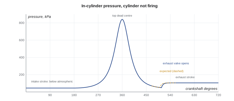
For an in-cylinder test, a high-pressure transducer is fitted into a spark plug hole with an adapter and a hose, the plug's ignition coil is left disconnected and that cylinder's injector disabled so the cylinder is not firing, and the engine is run at idle on the other cylinders. The transducer draws the pressure in the cylinder through the whole engine cycle: two crankshaft revolutions, 720 crankshaft degrees. Because the cylinder is not firing, the waveform shows only the effect of the piston and the valves, which is exactly what is needed to judge valve timing and sealing.
The waveform has a recognizable shape. The pressure rises to a peak as the piston compresses the trapped air, which marks top dead centre on the compression stroke. It falls symmetrically as the piston descends, until the exhaust valve opens near the bottom of the stroke, when the pressure drops quickly and a small change of slope marks the exhaust valve opening. Through the exhaust stroke the pressure stays slightly above atmospheric, with a small bump as the piston pushes the gas out. Near the top of the exhaust stroke the intake valve opens and the exhaust closes, the overlap period, and through the intake stroke the cylinder sits below atmospheric, at about the manifold vacuum. The intake valve closes after the bottom of the intake stroke, and compression begins again.
Finding valve events in degrees
A scope records time, not crankshaft degrees, but at a steady idle the engine turns at a constant speed, so time converts directly to degrees. At 700 rpm, the crankshaft turns 700 × 360 ÷ 60 = 4,200 degrees per second, so one degree takes about 0.24 milliseconds. The peak of the compression waveform marks top dead centre exactly, because the piston is at the top when the pressure is highest in a cylinder that is not firing. Measuring from the peak to the kink of the exhaust valve opening gives that event's timing in degrees after top dead centre. Scope software for in-cylinder testing often does this with cursors set to the peak; the code below does the same calculation on a sampled waveform.
# Find the exhaust valve opening on an in-cylinder waveform and express it in crankshaft degrees
import math
rpm = 700
deg_per_s = rpm * 360 / 60
rate = 50000                              # samples per second
def cyl_pressure(theta, evo):             # simple model of a cylinder that is not firing (illustrative)
    r = 9.5                               # compression ratio
    a = math.radians(theta - 360)
    vol = 1 + (r - 1) / 2 * (1 - math.cos(a))          # volume relative to the clearance volume
    p_comp = 45 * (r / vol) ** 1.3                      # compression starting from idle manifold vacuum
    if theta <= 360 + evo:
        return p_comp
    p_evo = 45 * (r / (1 + (r - 1) / 2 * (1 - math.cos(math.radians(evo))))) ** 1.3
    return 105 + (p_evo - 105) * math.exp(-(theta - 360 - evo) / 6)
evo_actual = 147                         # degrees after top dead centre on this engine
samples = []
for i in range(int(rate * 720 / deg_per_s)):
    theta = 180 + i / rate * deg_per_s     # start part way through the cycle
    samples.append(cyl_pressure(theta % 720, evo_actual))
peak_i = max(range(len(samples)), key=lambda i: samples[i])
slopes = [samples[i + 1] - samples[i] for i in range(len(samples) - 1)]
search = range(peak_i + int(60 / deg_per_s * rate), peak_i + int(200 / deg_per_s * rate))
kink = max(search, key=lambda i: abs(slopes[i]) - abs(slopes[i - int(3 / deg_per_s * rate)]))
evo_deg = (kink - peak_i) / rate * deg_per_s
spec = 141
print(f"peak pressure {samples[peak_i]:.0f} kPa at top dead centre")
print(f"exhaust valve opens {evo_deg:.0f} degrees after top dead centre; expected about {spec}")
print(f"difference: {evo_deg - spec:+.0f} crankshaft degrees ({(evo_deg - spec) / 2:+.0f} camshaft degrees)")peak pressure 840 kPa at top dead centre exhaust valve opens 147 degrees after top dead centre; expected about 141 difference: +6 crankshaft degrees (+3 camshaft degrees)
On Jess's engine, the exhaust valve opens about 6 crankshaft degrees later than the reference waveform for this engine shows, and Kiran finds the intake valve closing point about the same amount late. Both valve events are late by the same amount. That is the signature of a camshaft drive that has stretched or jumped: if one phaser were stuck, only its camshaft's events would move. Six crankshaft degrees is also exactly one tooth of the crankshaft wheel's 6-degree spacing, which matches the correlation code: the module sees the camshaft signal about one tooth late.
What else the in-cylinder waveform shows
The waveform also shows the cylinder's sealing. A cylinder that leaks makes a lower, narrower peak, and its pressure on the expansion side is lower than on the compression side at the same angle, because air escaped while the piston was at the top. A leaking exhaust valve, such as van 1's in Lesson 8, also shows a pressure rise during the intake stroke as exhaust gas leaks back. A restricted exhaust shows high pressure through the exhaust stroke. A sticking intake valve shows unusual pressure during the intake stroke. With a reference waveform from a known-good engine of the same type, many mechanical faults can be identified without dismantling anything.
| Waveform feature | Normal | What a fault looks like |
|---|---|---|
| Compression peak | Tall, symmetrical, similar on every cylinder | Low peak, lower on the expansion side: leaking cylinder |
| Exhaust valve opening | At the reference angle | Late or early with intake events also moved: camshaft drive fault |
| Exhaust stroke | Slightly above atmospheric | High pressure: restricted exhaust |
| Intake stroke | Below atmospheric, near manifold vacuum | Pressure rise: exhaust valve leak; odd shape: intake valve fault |
| Valve overlap | Small pocket near the top of the exhaust stroke | Shifted: camshaft timing; missing: valve or phaser fault |
Intake and exhaust pulse tests
A low-pressure transducer gives quicker, less precise screens. Connected to the intake manifold, it shows the vacuum pulsing as each cylinder draws in its charge. A cylinder with a leaking intake valve makes a pulse in the opposite direction as compressed gas escapes into the manifold. Held at the tailpipe, a sensitive transducer shows a pulse for each cylinder's exhaust; a misfiring cylinder makes a missing or reversed pulse, because its unburned charge leaves at lower pressure. With a cylinder 1 reference on a second channel, each pulse can be matched to a cylinder in the firing order, like the relative compression humps of Lesson 8. These tests take a few minutes and point the technician at the cylinder to test in detail.
A transducer on the fuel rail's test port, on a port injection engine, shows the rail pressure falling a little as each injector opens and recovering as the pump refills the rail. A cylinder's injector that does not open makes no dip; one that leaks makes the pressure fall when the engine is switched off. A pump that cannot keep up shows the whole waveform sagging under load, which is the fault in this course's capstone.
Jess's repair
With two independent tests agreeing, the in-cylinder waveform and the correlation code, and the scan data showing both camshafts on bank 1 equally late at idle, Kiran checks the camshaft and crankshaft sensor signals on the scope, as in Lesson 6, to rule out a sensor or wiring fault. Both signals are clean; the relationship between them is simply one tooth late. She then removes the valve cover and inspects the chain through the opening at the top: it is slack, and the tensioner is near the end of its travel. Jess's records show oil changes at nearly twice the recommended interval, which wears chains, guides and tensioners.
The repair is a timing chain kit, with the chain, guides, tensioner and sprockets, which Kiran fits under Marty's supervision following the engine course's procedure and the manufacturer's alignment marks. Afterward she repeats the in-cylinder test: the exhaust valve opening is within one degree of the reference. The correlation values in the scan data, which the module reports as the difference between expected and actual camshaft position at idle, now read close to zero, and the cold-start rattle has gone. Bev talks to Jess about oil change intervals, and Jess books her next one before she leaves.
Worked problem
Converting a measured time to crankshaft degrees
At a steady 750 rpm, the scope measures 32.4 milliseconds from the compression peak to the exhaust valve opening kink. How many degrees after top dead centre does the valve open?
Show solution
- Degrees per second = 750 × 360 ÷ 60 = 4,500.
- Degrees = 4,500 × 0.0324 = 145.8.
- Round to the scope's resolution.
Answer: About 146 degrees after top dead centre; compare with the reference waveform for the engine.
Cranking or running?
In-cylinder tests can be done while cranking or while running. A cranking test, with all the injectors disabled, shows the cylinder's compression and the valve events at a low, uneven speed, which makes the degree measurements less precise because the crankshaft speeds up and slows down with each compression stroke. A running test, at a steady idle with only the tested cylinder disabled, gives a steadier speed and more accurate timing, and a snap of the throttle shows how well the cylinder breathes at higher airflow. Kiran uses a cranking capture first, to confirm the cylinder seals, then a running capture for the valve timing. She also records which cylinder was tested and the engine speed on the capture, because a reference waveform is only useful when it was taken under the same conditions.
Common mistakes
MistakeRunning an in-cylinder test with the cylinder still firing.
InsteadDisconnect the coil and disable the injector so only the piston and valves shape the waveform.
MistakeMeasuring valve events at an unsteady engine speed.
InsteadTime converts to degrees only at a steady speed.
MistakeAssuming a correlation code means a stretched chain.
InsteadProve it: scope the sensors and check the valve events in the cylinder.
MistakeIgnoring whether a transducer reads gauge or absolute pressure.
InsteadCheck it at rest; at altitude the two differ by the local air pressure.
MistakeBlaming a phaser when every camshaft event moved by the same amount.
InsteadEqual shifts on both camshafts point at the chain drive, not one phaser.
Summary and key terms
- A pressure transducer turns pressure into a voltage the scope can draw.
- An in-cylinder waveform from a cylinder that is not firing shows top dead centre, valve events and sealing.
- At a steady speed, time converts to crankshaft degrees; the compression peak marks top dead centre.
- Events on both camshafts late by the same amount point at the camshaft drive.
- Low peaks and lower expansion-side pressure show a leaking cylinder.
- Intake vacuum and exhaust pulse tests quickly point at the faulty cylinder.
- Fuel rail pressure waveforms show injector openings and pump supply.
- Pressure transducer
- A sensor that converts a pressure into a proportional voltage.
- In-cylinder test
- A running test with a transducer in a spark plug hole of a cylinder that is not firing.
- Top dead centre
- The piston's highest point; on a cylinder that is not firing, the compression peak marks it.
- Exhaust valve opening
- The crankshaft angle at which the exhaust valve begins to open.
- Valve overlap
- The period when the intake and exhaust valves are both slightly open.
- Correlation
- The relationship between camshaft and crankshaft positions that a module checks.
Practice problems
Work each problem on paper first, then reveal the answer to check.
Why must the tested cylinder not fire during an in-cylinder test?
Show answer
So the waveform shows only the effect of the piston and valves.
What does it mean when both camshafts' events are late by the same amount?
Show answer
The camshaft drive, chain or belt, has stretched or jumped.
How many crankshaft degrees per second does an engine turn at 700 rpm?
Show answer
4,200.
What does a pressure rise during the intake stroke suggest?
Show answer
An exhaust valve leaking exhaust gas back into the cylinder.
Lesson quiz · 5 questions
Score 60% or more to complete this lesson.
Create a free account to save your progress, take quizzes and earn a certificate.