
AUTO-330 · Lesson 6 of 12 · 20 min
Scoping sensors: crank, cam, O2 and MAF
Gord Haney's pickup, now past 320,000 km (200,000 miles), has a new problem. Twice this month, after a long highway run on a hot afternoon, the engine stalled as he slowed for an exit and would not restart for ten minutes. Both times it started normally after cooling down. No codes are stored. "An engine that stops when hot and starts when cool has lost something it needs to run," Marty says. "Spark, fuel, or the module's sense of where the crankshaft is. Of those, the crankshaft signal is the one the scope can watch while you heat it."
This lesson shows how to scope the sensors that matter most for driveability: crankshaft and camshaft position sensors, both magnetic and Hall-effect types, their pattern and their relationship; oxygen and air-fuel ratio sensors; and mass airflow sensors. It explains what a good waveform looks like, what common faults look like, and how Kiran caught the pickup's stalling fault in the act.
Crankshaft position sensors
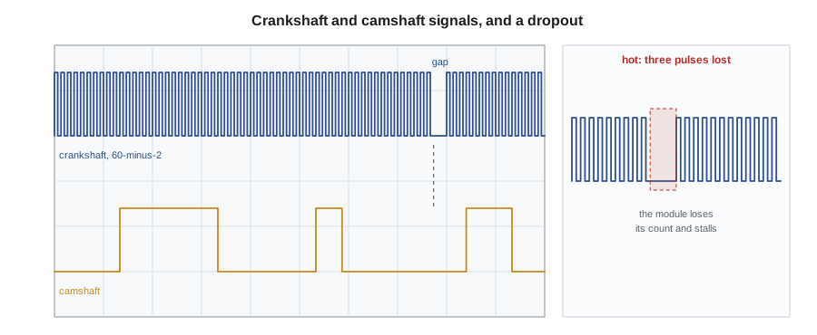
The engine control module needs to know the crankshaft's position and speed at every moment to time the spark and the injectors. A toothed wheel, called a reluctor or tone wheel, turns with the crankshaft, and a sensor next to it produces a signal as each tooth passes. One or two teeth are missing at a known position, so the module can find a reference point once each revolution. A common pattern is a wheel with 60 tooth positions and 2 missing, called 60-minus-2, which gives 58 actual teeth; Gord's engine uses this pattern. Other engines use 36-minus-1, 36-minus-2 or unique patterns with uneven spacing.
There are two main types of sensor. A magnetic, or variable reluctance, sensor has a magnet and a coil; each passing tooth changes the magnetic field and generates an alternating voltage. It needs no power supply, and its output gets larger and faster as engine speed rises, from about a volt peak-to-peak at cranking to tens of volts at high speed. The module detects the zero crossings of the signal. A Hall-effect sensor, or a magnetoresistive sensor, which works similarly, is powered by the module and switches its output between two fixed levels, usually near 0 and 5 volts or 0 and 12, giving a clean square wave whose height does not change with speed. Its signal is easier for a module to read at low speed, which is why most modern engines use one.
Camshaft position sensors and correlation
The crankshaft turns twice for every engine cycle, so its signal alone cannot tell the module whether a piston at the top of its stroke is on compression or exhaust. The camshaft turns once per cycle, and a camshaft position sensor reading a pattern of windows or teeth on the camshaft tells the module which revolution it is on. With both signals, the module can run sequential injection and coil-on-plug ignition. On engines with variable valve timing, the camshaft signals also tell the module the actual camshaft position for the timing control explained in Lesson 2.
Because both wheels are fixed to parts that are connected by the timing chain or belt, their signals have a fixed relationship when the timing is correct. A scope with both signals on two channels shows that relationship directly: a particular camshaft edge should fall at a particular crankshaft tooth after the gap. Manufacturers and scope suppliers publish known-good reference waveforms. A camshaft edge that falls a few teeth early or late points at a stretched or jumped timing chain, a worn sprocket or a wrong installation, the mechanical faults behind many camshaft and crankshaft correlation codes. Each crankshaft tooth on a 60-minus-2 wheel represents 6 crankshaft degrees, so one tooth of error is 6 degrees.
Detecting the gap and counting teeth
Scope software and engine control modules find the reference gap the same way: they measure the time between successive teeth and look for an interval much longer than its neighbours. At a steady speed, each tooth interval on a 60-minus-2 wheel is the same, and the gap is three times as long, because two teeth are missing. A module checks that it counts the right number of teeth between gaps; if it counts too few, it has lost teeth, and if that happens repeatedly it loses synchronization and stops the engine. The code below finds gaps and lost teeth in a series of tooth edge times, the same calculation the scope's analysis performs.
# Find the 60-minus-2 gap, count teeth per revolution, and detect lost pulses
rpm = 750
tooth_t = 60 / rpm / 60                   # time per tooth position, seconds
edges, t, missing_window = [], 0.0, range(140, 143)   # a dropout loses three pulses in revolution 3
n = 0
for rev in range(4):
    for pos in range(60):
        if pos >= 58:                     # the two missing teeth
            t += tooth_t; continue
        if n in missing_window:
            t += tooth_t; n += 1; continue
        edges.append(t); t += tooth_t; n += 1
gaps = []
for i in range(1, len(edges) - 1):
    this, prev = edges[i] - edges[i - 1], edges[i - 1] - edges[i - 2] if i > 1 else edges[1] - edges[0]
    if this > 2.5 * prev:
        gaps.append(i)
for a, b in zip(gaps, gaps[1:]):
    teeth = b - a
    note = "ok" if teeth == 58 else "WRONG: lost pulses look like an extra gap, so the module loses sync"
    print(f"teeth between gaps: {teeth:2}  {note}")
print(f"tooth interval at {rpm} rpm: {tooth_t * 1000:.2f} ms, gap {3 * tooth_t * 1000:.2f} ms")teeth between gaps: 58 ok teeth between gaps: 24 WRONG: lost pulses look like an extra gap, so the module loses sync teeth between gaps: 31 WRONG: lost pulses look like an extra gap, so the module loses sync tooth interval at 750 rpm: 1.33 ms, gap 4.00 ms
The program shows what a dropout does to the count. The first revolution has the correct 58 teeth. In the third, three lost pulses leave a space even longer than the real gap, so the count finds a gap where there is none and the tooth totals come out wrong on both sides of it. Either way, the module loses track of the crankshaft and stops the injectors and coils until it can find the gap again.
Catching Gord's fault
Kiran plans a test that reproduces the conditions: a hot engine. She connects channel 1 to the crankshaft sensor's signal wire and channel 2 to the camshaft sensor's, back-probing both at the sensors, and channel 3 to the crankshaft sensor's power supply wire. She uses the scope's long recording mode, which stores many seconds of data at a high sample rate, and sets a trigger that fires if the time between crankshaft edges exceeds four tooth intervals, longer than the normal gap. She then drives the pickup on the highway for half an hour with the scope running on the passenger seat, while Marty drives.
On the exit ramp, the engine stumbles but does not stall, and the scope triggers. The capture shows the crankshaft signal missing three pulses, then a burst of short, uneven pulses, then normal teeth. The camshaft signal and the sensor's power supply stay perfect throughout. A power supply problem or a wiring short would usually affect more than one signal, and a reluctor wheel fault would repeat at the same position every revolution. A crankshaft sensor that fails only when hot, while its power is good, points at the sensor itself. Kiran confirms it in the bay: with the engine idling and hot, she warms the sensor further with a heat gun on low, held at a safe distance, and the pulses drop out again at the same temperature. Cooling the sensor with a damp rag restores them.
The repair is a new crankshaft sensor, fitted with the manufacturer's procedure, which on this engine includes a crankshaft position variation relearn so the module can learn the small differences between teeth that it uses to detect misfires. Kiran then repeats the hot test with the heat gun and a highway drive with the scope recording, with no dropouts. She saves the good waveform in the shop's reference folder.
Oxygen and air-fuel ratio sensors
The emissions course explained how oxygen sensors control fuel. On a scope, a healthy zirconia oxygen sensor upstream of the catalyst switches between about 0.1 volts, lean, and 0.8 or 0.9 volts, rich, several times per second at 2,500 rpm, with quick transitions between the two. A slow, lazy sensor takes longer to switch and spends less time at the extremes; a contaminated sensor may stay biased high or low. The time it takes to go from lean to rich, measured between about 300 and 600 millivolts, is a useful check: on a good sensor it is well under 100 milliseconds, and Mode 06 often reports the module's own measurement of the same thing.
Air-fuel ratio sensors, also called wideband sensors, are used upstream on most newer engines. Their output is a current that the module converts into an air-fuel ratio or lambda value. A scope cannot read them directly in a meaningful way without the manufacturer's procedure, so they are usually tested with scan data: the reported lambda should respond quickly to a change, such as a brief snap of the throttle or a propane enrichment, and should read accurately at a known condition.
# Analyse a recorded upstream oxygen sensor signal: switching rate and lean-to-rich transition time
import math
rate = 1000                                      # samples per second
v = []
for i in range(2000):                            # two seconds at 2,500 rpm
    t = i / rate
    s = math.sin(2 * math.pi * 1.6 * t)          # about 1.6 rich-lean cycles per second
    v.append(0.45 + 0.40 * math.tanh(4 * s))     # switches between about 0.05 and 0.85 volts
crossings = sum(1 for a, b in zip(v, v[1:]) if (a - 0.45) * (b - 0.45) < 0)
rises = []
i = 0
while i < len(v) - 1:
    if v[i] < 0.3 <= v[i + 1]:
        j = i + 1
        while j < len(v) and v[j] < 0.6:
            j += 1
        rises.append((j - i) / rate * 1000)
        i = j
    i += 1
print(f"switches across 0.45 V: {crossings} in 2 s ({crossings / 2:.1f} per second)")
print(f"lean-to-rich transitions, 300 to 600 mV: {', '.join(f'{r:.0f}' for r in rises)} ms")
print(f"lowest {min(v):.2f} V, highest {max(v):.2f} V")switches across 0.45 V: 6 in 2 s (3.0 per second) lean-to-rich transitions, 300 to 600 mV: 20, 20, 20 ms lowest 0.05 V, highest 0.85 V
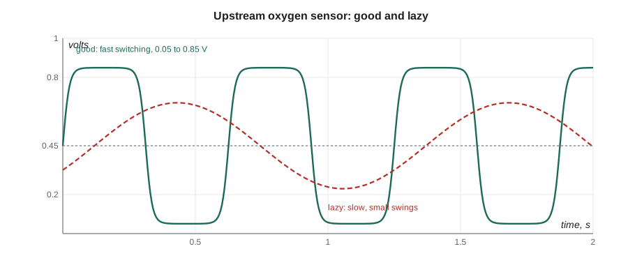
The sample sensor crosses the midpoint about three times per second, swings between about 0.05 and 0.85 volts and moves from 300 to 600 millivolts in about 20 milliseconds: a good sensor. Kiran compares this with the sensor on Hal's van 1 from Lesson 3, whose Mode 06 response time was close to its limit; its waveform takes noticeably longer to switch, and Bev adds it to the van's list of recommended work.
Mass airflow sensors
Most mass airflow sensors heat a thin element in the incoming air and measure how much power it takes to hold its temperature; more air carries away more heat. Some report airflow as a voltage, usually from about 1 volt at idle to 4 or more at full throttle; many newer ones report it as a frequency, often a few kilohertz, rising with airflow. On a scope, a good sensor's signal follows a throttle snap smoothly and quickly, rising sharply as the throttle opens, overshooting slightly as the intake fills, and settling. A sensor with a contaminated element responds slowly and reads low at high airflow, the fault Kiran found on Harold Kemp's SUV in the emissions course. A signal with sudden spikes or drops at a steady airflow points at a wiring or connector fault.
A frequency-output sensor must be read with the scope's frequency measurement or a meter's frequency function, because a meter's voltage reading of a square wave means nothing useful. Kiran checks the frequency at idle and at a steady 2,500 rpm against the service information's table, then compares the scan tool's grams per second with the expected airflow calculation from Lesson 3.
| Sensor | Good waveform | Common fault on the scope |
|---|---|---|
| Magnetic crank sensor | Alternating signal growing with speed; clear gap | Low amplitude from a wide air gap or a weak magnet; noise from damaged wiring |
| Hall crank or cam sensor | Clean square wave, fixed height, sharp edges | Missing pulses when hot; rounded edges or a low top level from a power or ground fault |
| Zirconia oxygen sensor | Switching 0.1 to 0.9 volts several times a second, fast transitions | Slow, lazy switching; biased high or low |
| Mass airflow sensor | Smooth, quick rise on a throttle snap, steady at constant airflow | Slow rise, low peak, spikes or dropouts |
Worked problem
Converting tooth error to timing error
On a 60-minus-2 crankshaft wheel, the camshaft edge that should fall 14 teeth after the gap falls 15 teeth after it. How far is the camshaft out, in crankshaft and camshaft degrees?
Show solution
- Each tooth position is 360 ÷ 60 = 6 crankshaft degrees.
- One tooth late is 6 crankshaft degrees.
- The camshaft turns at half crankshaft speed, so 6 crankshaft degrees is 3 camshaft degrees.
Answer: 6 crankshaft degrees, or 3 camshaft degrees, retarded: check the timing chain, sprockets and tensioner.
Common mistakes
MistakeMeasuring a crank sensor's resistance and calling it good.
InsteadA sensor can pass a resistance test cold and drop out hot; scope it under the failing conditions.
MistakeScoping only the crankshaft signal.
InsteadScope crank, cam and the sensor's power together to separate sensor, wiring and timing faults.
MistakeExpecting a magnetic sensor's signal to be the same height at all speeds.
InsteadIts amplitude rises with speed; a Hall sensor's does not.
MistakeReading a frequency-output sensor with a meter's voltage setting.
InsteadUse a frequency measurement or the scope.
MistakeSkipping the relearn after replacing a crank sensor.
InsteadMany engines need a crankshaft variation relearn for misfire detection.
Summary and key terms
- A toothed wheel with missing teeth gives the module crankshaft position, speed and a reference once per revolution.
- Magnetic sensors produce an alternating signal that grows with speed; Hall sensors switch between fixed levels.
- The camshaft signal tells the module which revolution it is on; its relationship to the crank signal shows timing.
- Each tooth on a 60-minus-2 wheel is 6 crankshaft degrees.
- Lost pulses make the module lose synchronization and stop the engine.
- A good zirconia sensor switches quickly between about 0.1 and 0.9 volts.
- A mass airflow sensor should follow a throttle snap smoothly and quickly.
- Reluctor wheel
- A toothed wheel whose passing teeth a position sensor detects.
- 60-minus-2
- A crankshaft wheel pattern of 60 tooth positions with 2 missing.
- Variable reluctance sensor
- A magnetic sensor that generates an alternating voltage as teeth pass.
- Hall-effect sensor
- A powered sensor that switches its output between two fixed levels as a magnetic field changes.
- Synchronization
- The module's knowledge of exactly where the crankshaft is in the engine cycle.
- Wideband sensor
- An air-fuel ratio sensor that reports the mixture over a wide range as a current.
- Crankshaft variation relearn
- A procedure in which the module learns small tooth-spacing differences for misfire detection.
Practice problems
Work each problem on paper first, then reveal the answer to check.
Why did Kiran scope the crank sensor's power supply as well as its signal?
Show answer
To tell a power or wiring fault, which would affect more than one signal, from a sensor fault.
How long is the gap on a 60-minus-2 wheel compared with a normal tooth interval?
Show answer
Three times as long.
What does a lazy oxygen sensor look like on a scope?
Show answer
Slow transitions and less time at the rich and lean extremes.
Why did the pickup restart after cooling?
Show answer
The crankshaft sensor's fault appeared only when it was hot.
Lesson quiz · 5 questions
Score 60% or more to complete this lesson.
Create a free account to save your progress, take quizzes and earn a certificate.