
AUTO-130 · Lesson 3 of 12 · 22 min
Master cylinders, lines, hoses and valves
Gord Haney's pickup comes in on a Thursday with its red brake warning lamp lit. Gord had pulled into a parking lot, felt the pedal sink much further than normal, and seen a wet spot under the truck. He drove the last few kilometres to Ridgeline slowly, in low gear, using the parking brake to help. Simone books it straight in, and Marty puts Kiran on it with one condition: “Find the leak, then tell me why it happened and why the truck still stopped at all.”
On the lift, the cause is easy to find. The steel line that carries fluid to the rear axle has rusted through where it runs above the frame rail next to the fuel tank, under a plastic clip that held salty slush against it for twelve winters. Calgary's chinooks melt and refreeze the road salt on the streets over and over, and the brine finds every crevice. This lesson explains the parts that carry pressure from the pedal to the wheels: the master cylinder and its reservoir, the two separate hydraulic circuits, the steel lines and their fittings, the flexible hoses, and the valves that control pressure. It also explains how each part fails and how it is tested.
The master cylinder
Every modern master cylinder is a tandem design: one bore containing two pistons, one behind the other, each feeding its own circuit. The pushrod pushes the primary piston, at the rear. A spring and the fluid trapped between the two pistons push the secondary piston, at the front. Each piston carries rubber cup seals, and each section of the bore has two small holes into the reservoir above: a compensating port just ahead of the piston's cup seal, and a larger inlet or replenishing port behind it.
When the pedal is released, the pistons rest just behind their compensating ports, so each circuit is open to the reservoir. That matters: as the brakes heat up and the fluid expands, or as the pads wear and the caliper pistons move out, fluid can flow freely between the circuit and the reservoir, and no pressure builds up while the brakes are off. When the driver presses the pedal, each piston's cup seal moves past its compensating port and closes it, and from then on the piston pressurizes the fluid ahead of it. When the pedal is released quickly, fluid can flow from behind the piston, through the inlet port, past the lip of the cup seal, so the piston returns without pulling a vacuum.
If the pushrod is adjusted too long, or the pedal does not return fully, the pistons cannot uncover their compensating ports. Pressure then stays trapped in the system, and as the brakes heat up the pressure rises and the brakes drag, sometimes until they lock. That is why the pushrod clearance is checked whenever a booster or master cylinder is replaced.
The reservoir sits on top of the master cylinder, usually made of translucent plastic with MIN and MAX marks, and divided inside so that a leak in one circuit cannot drain the fluid of the other. A float switch in the reservoir turns on the red brake warning lamp when the level drops. The level falls slowly as the pads wear, because the caliper pistons move out and hold more fluid, so a level at MIN on a car with worn pads is normal; topping it up then would overfill it when new pads push the pistons back. A level that falls quickly means a leak.
Two circuits: front-rear and diagonal splits
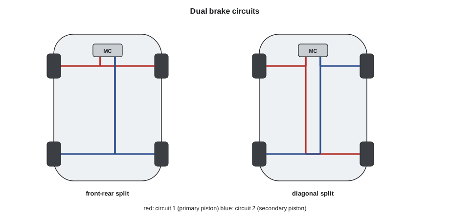
Since the late 1960s, light vehicles have been required to have a dual hydraulic system, so that a single leak cannot remove all braking. There are two common layouts. In a front-rear split, one circuit feeds both front brakes and the other both rears. This suits vehicles with rear-wheel drive and a lot of weight at the rear when loaded, including most pickups and vans, and Gord's truck. In a diagonal split, each circuit feeds one front wheel and the diagonally opposite rear wheel. Most front-wheel-drive cars use it, because their front brakes do so much of the work that losing both fronts would leave very little braking.
When one circuit fails, the pedal travels further, because the primary piston has to move until it touches the secondary piston, or the secondary piston has to bottom in the bore, before pressure can build in the remaining circuit. The driver feels a low pedal and gets less braking. A pressure differential switch, often in the same housing as the proportioning valve, senses unequal pressure between the circuits and turns on the red warning lamp; on modern vehicles the anti-lock controller or the reservoir float usually does this job instead.
# What is left when one circuit fails (braking shares from Lesson 2's style of calculation)
UNITS = "metric"
layouts = {
    "front-rear split, rear circuit lost (Gord's truck)": {"front": 0.70, "rear": 0.00},
    "front-rear split, front circuit lost":               {"front": 0.00, "rear": 0.30},
    "diagonal split, one diagonal lost (typical car)":   {"front": 0.38, "rear": 0.12},
}
full_decel = 0.80                                  # g with both circuits on a dry road
for name, share in layouts.items():
    left = share["front"] + share["rear"]
    print(f"{name:<52} about {left * 100:3.0f} % of the braking force, roughly {full_decel * left:.2f} g")
print("the remaining circuit also needs extra pedal travel before it builds pressure")front-rear split, rear circuit lost (Gord's truck) about 70 % of the braking force, roughly 0.56 g front-rear split, front circuit lost about 30 % of the braking force, roughly 0.24 g diagonal split, one diagonal lost (typical car) about 50 % of the braking force, roughly 0.40 g the remaining circuit also needs extra pedal travel before it builds pressure
Gord's truck lost its rear circuit, so it still had its front brakes, which do most of the work. That is why he could stop, slowly and with a long pedal, and why the design requirement for two circuits exists. It does not make a failed circuit safe to drive on; the truck should have been towed.
Testing a master cylinder
A master cylinder can leak externally, at the rear seal into the booster or at the reservoir grommets, or internally, when a worn cup seal lets fluid slip past the piston from the pressure side back to the reservoir side. An internal leak, called bypassing, shows as a pedal that slowly sinks under steady foot pressure with no fluid lost anywhere. To test for it, the technician holds steady, moderate pressure on the pedal with the engine off for about thirty seconds. A good system holds the pedal still. A pedal that creeps down, with no external leak and no fluid loss, points to bypassing, although an anti-lock unit with a leaking valve can do the same, so the test is repeated with the lines to the anti-lock unit capped off if the vehicle's procedure allows it.
A new or rebuilt master cylinder is bench bled before installation: it is clamped level in a vice, fitted with bleeder tubes that return its outlets into the reservoir, and stroked until no air comes out. This saves a great deal of bleeding later and avoids pushing air into the anti-lock unit, which can be very hard to get out. Lesson 4 describes bleeding in detail.
# Pedal hold test: steady pressure, engine off, readings of pedal height from the floor
UNITS = "metric"
readings = [(0, 118), (10, 118), (20, 117), (30, 117)]   # seconds, pedal height in mm
drop = readings[0][1] - readings[-1][1]
for t, h in readings:
    print(f"{t:>3} s: {h} mm")
if drop <= 3:
    print("pedal holds: no internal leak")
else:
print(f"pedal dropped {drop:.1f} mm in 30 s: check for external leaks; if none, suspect master cylinder bypass or an ABS valve")0 s: 118 mm 10 s: 118 mm 20 s: 117 mm 30 s: 117 mm pedal holds: no internal leak
With the new rear line installed, Gord's pedal holds steady, so the master cylinder is not bypassing; it simply lost fluid through the hole in the line.
Steel brake lines
Brake lines are seamless or double-wall steel tubing, coated to resist corrosion, because they must hold pressures of more than 10 megapascals for the life of the vehicle. Most light vehicles use lines of 4.75 mm outside diameter, with some 6.35 mm lines from the master cylinder. Replacement lines are available in coated steel and in copper-nickel alloy, which bends easily by hand and resists corrosion very well; plain copper tubing is never used because it work-hardens and cracks. The line must be the same diameter as the original and must be secured with clips at the original points, away from the exhaust, moving parts and sharp edges.
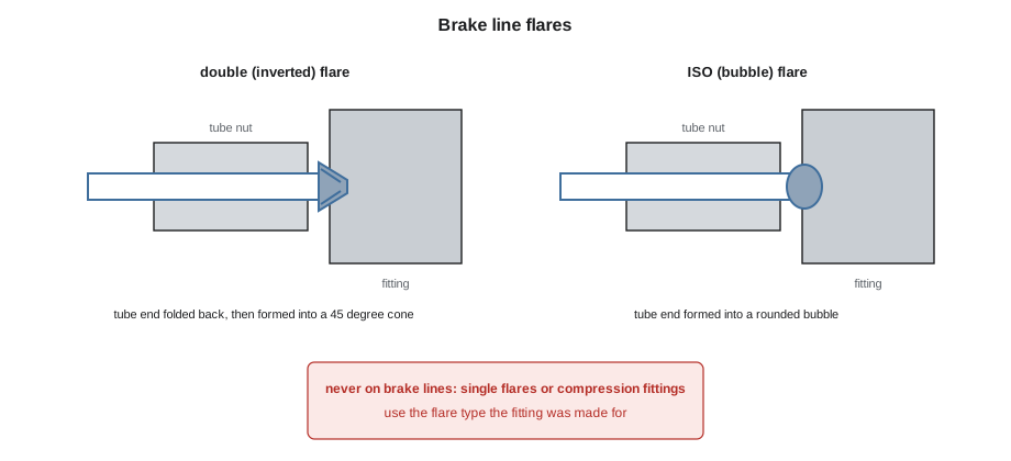
Lines are joined to components with flared ends and tube nuts. Two flare types are used on modern vehicles, and they are not interchangeable. The SAE double flare, also called the inverted flare, has the end of the tube folded back on itself and then formed into a 45-degree cone, which seats inside a matching cone in the fitting. The ISO flare, also called the bubble flare, forms the tube end into a rounded bubble that seats against a shallow cone; it is common on European and many Asian vehicles and on some domestic ones. A single flare, a simple cone without the fold, is not strong enough for brakes and cracks. Compression fittings, which seal by squeezing a ferrule onto the tube, are never used in brake systems, whatever a parts counter may offer.
Kiran cuts out the rusted section with a tubing cutter, which leaves a square end, deburrs the inside and outside, slides the correct tube nuts on before flaring, and makes double flares with a flaring tool in the vice, using the tool's die to fold the end before forming the cone. She bends the new line with a tubing bender to follow the original route, and joins it to the good section with a union fitting of the same flare type. Marty inspects the rest of the lines on the truck and finds the front lines in fair condition but the rear axle lines scaled with rust. He prices both the repair and a complete rear line replacement for Gord, because a line that has rusted through in one spot is often thin elsewhere.
# Bill of materials for Gord's rear brake line repair
UNITS = "metric"
sections = [("frame rail, fuel tank to rear crossmember", 1650), ("rear crossmember to axle hose", 520)]
bends = 9
extra = 80                       # allowance for flares and routing, mm per section
total = sum(l for _, l in sections) + extra * len(sections)
for name, l in sections:
    print(f"{name:<44} {l} mm")
print(f"tubing needed with allowance: {total} mm of 4.75 mm line, {bends} bends")
print("fittings: 2 unions (double flare), 4 tube nuts, 3 clips; flare type checked at each fitting")frame rail, fuel tank to rear crossmember 1650 mm rear crossmember to axle hose 520 mm tubing needed with allowance: 2330 mm of 4.75 mm line, 9 bends fittings: 2 unions (double flare), 4 tube nuts, 3 clips; flare type checked at each fitting
Brake hoses
Lines cannot move, but wheels do: they steer and they move up and down with the suspension. Flexible hoses connect the body-mounted lines to each front caliper and to the rear axle or rear calipers. A brake hose is made of layers of rubber with braided reinforcement, and it must hold full pressure without swelling much, because swelling uses up fluid volume and lengthens the pedal travel. Hoses are attached to calipers either with a threaded end or with a banjo fitting, a hollow bolt through a round fitting, sealed by two soft copper washers that are always replaced with new ones.
Hoses deteriorate with age, heat and salt. The outside can crack, chafe or bulge, which is easy to see. The inside is harder to judge: the inner layer can delaminate and form a flap that acts like a one-way valve, letting pressure reach the caliper but not letting the fluid return. The brake on that wheel then drags after the pedal is released, often making the vehicle pull to that side under braking and the wheel hotter than the others. A technician who finds one wheel dragging opens that caliper's bleeder screw; if the caliper suddenly releases, the restriction is upstream, often in the hose, not in the caliper.
Hoses must be installed without twists, because a twisted hose tries to unwind as the suspension moves and can rub or pull loose. Most have a stripe along their length to show any twist. A hose must never be left supporting the weight of a caliper; when a caliper is removed for pad work, it is hung from the suspension with a wire hook.
Pressure control valves
Older vehicles, and some current trucks without full electronic brake force distribution, use valves to adjust the pressure to the front or rear brakes. A proportioning valve in the rear circuit lets full pressure through up to a split point and then lets only a fraction of any further increase through, so that the rear wheels do not lock as weight moves forward in a hard stop. A load-sensing proportioning valve, linked to the rear axle by a lever and spring, raises the split point when the truck is loaded and the body sits lower. A metering valve, used on vehicles with front discs and rear drums, holds off front pressure for the first few hundred kilopascals, so that the rear shoes, which need pressure to overcome their return springs, contact their drums at the same time as the front pads. A combination valve houses two or three of these functions in one body, often with the pressure differential switch.
On most vehicles built since the 2000s, the anti-lock controller performs all these jobs electronically. Electronic brake force distribution reduces rear pressure only when the rear wheels start to slip more than the fronts, so it adapts to load, road surface and tire condition automatically. Gord's truck uses electronic distribution; its old load-sensing valve bracket is still on the frame from an earlier design but is empty.
# A proportioning valve: rear pressure versus front pressure (split point and slope are illustrative)
UNITS = "metric"
split = 3000          # kPa
slope = 0.40             # fraction of the increase passed to the rear above the split point
for front in (1000, 3000, 5000, 8000, 10000):
    rear = front if front <= split else split + slope * (front - split)
print(f"front {front:6} kPa -> rear {rear:6.0f} kPa")front 1000 kPa -> rear 1000 kPa front 3000 kPa -> rear 3000 kPa front 5000 kPa -> rear 3800 kPa front 8000 kPa -> rear 5000 kPa front 10000 kPa -> rear 5800 kPa
Worked problem
Why did Gord's pedal sink, and why did he still stop?
Explain the failure to Gord in plain terms, and say what Ridgeline recommends.
Show solution
- The steel line to the rear brakes rusted through under a clip, so the rear circuit lost its fluid and could not build pressure.
- The master cylinder has two separate circuits; the front circuit was undamaged, so the front brakes still worked, but the pedal had to travel further before they applied.
- The red warning lamp came on because the reservoir level dropped.
- The repaired line and a full bleed restored normal braking; the pedal hold test shows the master cylinder is good.
- Because the other rear lines are heavily rusted, Ridgeline recommends replacing them before next winter, and rinsing the underside during the salt season.
Answer: One circuit failed and the other carried him; the line is repaired, and the remaining rusty lines should be replaced soon.
Common mistakes
MistakeTopping up the reservoir as pads wear.
InsteadA falling level with worn pads is normal; check for leaks, then service the pads.
MistakeUsing a compression fitting or single flare on a brake line.
InsteadUse the original flare type, double or ISO, made with the correct tool.
MistakeReusing banjo bolt washers.
InsteadFit new copper washers every time.
MistakeLetting a caliper hang on its hose.
InsteadSupport it with a wire hook.
MistakeInstalling a twisted hose.
InsteadUse the stripe to install it straight.
Summary and key terms
- A tandem master cylinder has two pistons feeding two separate circuits.
- Compensating ports let fluid flow to and from the reservoir when the brakes are off; a long pushrod blocks them and causes drag.
- Front-rear and diagonal splits keep some braking if one circuit fails, at the cost of a longer pedal.
- A slowly sinking pedal with no external leak suggests master cylinder bypassing.
- Brake lines are coated steel or copper-nickel with double or ISO flares, never compression fittings.
- Hoses can crack outside or collapse inside, causing drag and pulls.
- Proportioning, metering and load-sensing valves are being replaced by electronic brake force distribution.
- Tandem master cylinder
- A master cylinder with two pistons in one bore, each feeding its own circuit.
- Compensating port
- A small hole that connects a circuit to the reservoir when the brakes are released.
- Diagonal split
- A layout in which each circuit serves one front wheel and the opposite rear wheel.
- Bypassing
- Internal leakage of fluid past a master cylinder piston seal.
- Double flare
- A tube end folded back on itself and formed into a 45-degree cone.
- Banjo fitting
- A round hose fitting held by a hollow bolt and sealed with copper washers.
- Proportioning valve
- A valve that limits rear brake pressure above a split point.
Practice problems
Work each problem on paper first, then reveal the answer to check.
What happens to the pedal when one circuit of a dual system fails?
Show answer
It travels further before the remaining circuit builds pressure, and braking is reduced.
Why is a falling reservoir level not always a leak?
Show answer
As pads wear, caliper pistons move out and hold more fluid.
A wheel drags but releases when its bleeder is opened. What is the likely cause?
Show answer
A restriction upstream, often a collapsed hose.
Why are compression fittings never used on brake lines?
Show answer
They are not designed for brake pressures and can leak or blow off.
Lesson quiz · 5 questions
Score 60% or more to complete this lesson.
Create a free account to save your progress, take quizzes and earn a certificate.