
ARCH-320 · Lesson 8 of 12 · 21 min
Electrical systems
Harjit Sandhu, an electrical engineer who designs power systems for apartment buildings and hospitals, visits in week eight. She brings two things: a piece of copper bus bar as thick as a textbook, from the main switchboard of a tower she worked on, and a printed email from a utility. 'The bus bar is what electricity looks like when a whole building's worth of it goes through one place,' she says. 'The email is from the utility, telling a client that their new building, all-electric, with heat pumps and car chargers, needs a bigger transformer than the street can supply, and the upgrade will take eighteen months. Electrification is the best thing that has happened to building emissions, and it has made electrical service the first thing you should ask about on a new project.' This lesson covers how power reaches a building, how it is distributed inside and what space that takes.
Basic quantities
Electrical systems are described by a few quantities. Voltage, in volts, is the electrical pressure that drives current; current, in amperes (amps), is the rate of flow of charge; power, in watts, is the rate at which energy is used. In alternating-current systems, the apparent power that conductors and transformers must carry is measured in volt-amperes (VA) or kilovolt-amperes (kVA), slightly more than the real power in watts when loads such as motors draw current out of step with the voltage. The ratio is the power factor.
Buildings larger than houses use three-phase power, which delivers power smoothly and efficiently through three conductors whose voltages peak at different times. The current a conductor must carry, for the same power, falls as the voltage rises, which is why large buildings take power at higher voltages and step it down near the loads. In Canada, the common building voltages are 120/240 V single phase for houses, 120/208 V three phase for apartments and small commercial buildings, and 347/600 V three phase for larger buildings, a distinctly Canadian voltage that lets lighting run at 347 V and motors at 600 V.
From the utility to the building
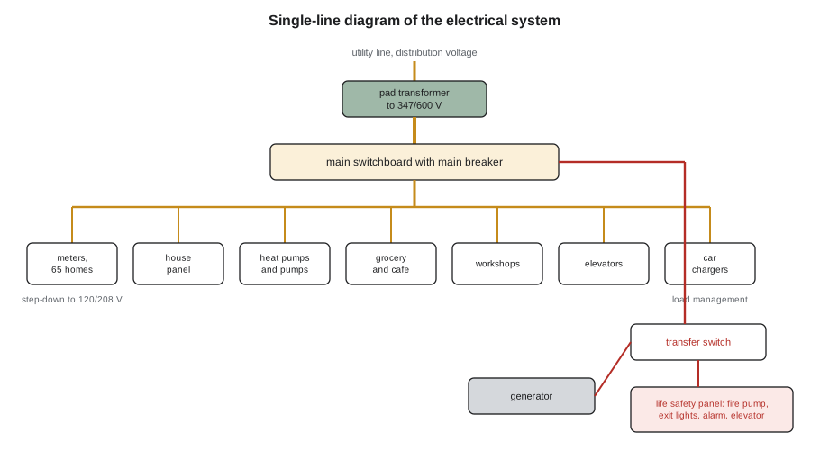
The utility, Manitoba Hydro in Winnipeg, brings power at distribution voltage, thousands of volts, in overhead lines or underground cables. A transformer steps it down to the building's service voltage. For a building of the Riverlot building's size, the transformer is usually a pad-mounted unit outdoors, a green steel box about the size of a small car on a concrete pad, owned by the utility, with clearances around it for access and fire safety set by the utility's standards. In dense downtown sites without room for a pad, the transformer may go in a vault inside the building, with fire-rated walls, ventilation and direct access for utility crews, which takes valuable ground-floor space.
From the transformer, service conductors run to the building's main switchboard in the main electrical room. The switchboard contains the main disconnect, which can cut power to the whole building, and the overcurrent protection for each major feeder. Meters for the utility are at the service: one for each home and tenant, typically grouped on a meter stack in a meter room, plus a house meter for common loads. Electrical work follows the Canadian Electrical Code, CSA C22.1, whose 26th edition Manitoba adopted by regulation in 2026, with Manitoba amendments.
Estimating the service
The service must be large enough for the building's peak demand, which is much less than the sum of every connected load, because they do not all run at once. Codes give demand factors for dwellings and many other loads, and engineers use measured data from similar buildings. Electrification raises the demand: heat pumps, heat pump water heaters, induction ranges and car chargers add large loads that older buildings served with gas did not have. Sandhu walks the students through a first estimate for the Riverlot building, with studio demand values.
# First estimate of the Riverlot building's electrical service (studio demand values)
import math
demand = {                                   # load: kVA at the building peak
    "65 homes (lighting, cooking, laundry, fan coils)": 65 * 3.5,
    "central heat pumps, coldest night":         160,
    "electric backup heat":                       60,
    "heat pump water heaters and pumps":          30,
    "grocery (refrigeration, lighting)":         120,
    "cafe kitchen":                               40,
    "workshops":                                  60,
    "elevators (two passenger, one freight)":     45,
    "ventilation, common areas, exterior":        40,
    "20 car chargers with load management":       20 * 7.2 * 0.5,
}
total = sum(demand.values())
for k, v in demand.items():
    print(f"{k:48s} {v:6.0f} kVA")
print(f"estimated peak demand {total:,.0f} kVA")
for volts in (600, 208):
    amps = total * 1000 / (math.sqrt(3) * volts)
    print(f"at {volts} V three phase: {amps:,.0f} A")
print("transformer: next standard size above the demand, with room to grow, about 1,000 kVA")65 homes (lighting, cooking, laundry, fan coils) 228 kVA central heat pumps, coldest night 160 kVA electric backup heat 60 kVA heat pump water heaters and pumps 30 kVA grocery (refrigeration, lighting) 120 kVA cafe kitchen 40 kVA workshops 60 kVA elevators (two passenger, one freight) 45 kVA ventilation, common areas, exterior 40 kVA 20 car chargers with load management 72 kVA estimated peak demand 854 kVA at 600 V three phase: 822 A at 208 V three phase: 2,372 A transformer: next standard size above the demand, with room to grow, about 1,000 kVA
The estimate is about 850 kVA. At 600 V, that is about 820 A; at 208 V it would be about 2,400 A, nearly three times as much, needing much heavier conductors and switchgear. Engineers would therefore bring the service in at the higher voltage and use step-down transformers on the residential floors or in the electrical rooms to supply 120/208 V to the homes. The largest single items are the homes together and the heat pump plant on the coldest night, with its backup heat. The backup heat from lesson 4 alone adds 60 kVA, which is why Ingrid's storage tank and third heat pump at the hub mattered: reducing the coldest-night peak reduces the service, the transformer and sometimes the utility upgrade.
Car chargers are a new and growing load. Twenty chargers at 7.2 kW each would add almost 150 kVA if they all ran at once; load management systems share the available capacity among the cars plugged in, so that each gets a full charge overnight without a large peak. Many cities now require new buildings to install chargers or the conduit for them.
Distribution inside the building
From the main switchboard, feeders run to distribution panels and panelboards around the building, and branch circuits run from the panels to receptacles, lights and equipment. Large buildings stack an electrical room or closet on each floor, one above the other, connected by a riser of cables or a busway, a set of copper or aluminium bars in a metal enclosure that can be tapped on each floor. Each home in the Riverlot building has its own panel, usually in the entry closet, fed from the meter room; corridors, stairs and common areas are fed from house panels.
Electrical rooms need space, clearances and conditions that architects must provide. Codes require working space in front of switchboards and panels, typically about 1 m deep, and two exits from rooms containing large switchboards, so that a worker can escape an arc flash. Rooms must be dry, away from water pipes passing overhead, ventilated to remove the heat transformers give off, and accessible for replacing equipment. They are not storage rooms, though they often become them.
| Space | Typical size for the Riverlot building | Location |
|---|---|---|
| Main electrical room | 35 to 45 m², two exits | At grade on the lane, beside the transformer pad |
| Meter room | 15 to 20 m² for about seventy meters | Next to the main electrical room |
| Floor electrical closets | 4 to 6 m² each, stacked | Beside the core on each floor |
| Generator | about 20 m² with clearances, plus fuel | On the roof or at grade outdoors, away from windows and intakes |
| Main telecom room | 10 to 12 m² | At grade, near the service entrance of the telecom providers |
| Transformer pad | about 3 × 3 m with clearances | Outdoors on the lane, reachable by utility trucks |
Emergency and standby power
Some loads must keep running when utility power fails. Life safety loads, which codes require, include exit signs and emergency lighting, the fire alarm, the fire pump, smoke control fans and at least one elevator for firefighters. Other loads are optional standby: refrigeration in the grocery, which could lose thousands of dollars of food in a long outage; the heat pumps, to keep homes from freezing in a winter outage; and communications. Emergency power comes from a generator, batteries or both, connected through automatic transfer switches that switch the loads over within seconds.
Generators are large, heavy, noisy and need fuel and exhaust. A diesel generator for the Riverlot building's life safety loads and some standby loads would be about the size of a delivery van, with a fuel tank for a day or more of running, exhaust well away from windows and air intakes, and sound attenuation. Placing it on the roof keeps exhaust away from people but adds weight and needs a way to bring fuel up; placing it at grade needs space and screening. Natural gas generators avoid fuel storage but rely on the gas supply. Batteries can carry emergency lighting and alarms for the required hours, and larger battery systems, sometimes paired with rooftop solar panels, are beginning to replace generators for some standby loads.
Solar power and the future grid
Rooftop solar photovoltaic panels can supply part of a building's electricity. On a building like the Riverlot building, the roof is crowded with heat pumps, exhaust fans, the generator and terraces, so the available area for panels is limited, perhaps 200 m², which might produce a small share of the building's annual electricity. Panels can also form part of the facade or canopies. Manitoba's grid is almost entirely hydroelectric, so the carbon benefit of solar is small, though it can reduce bills. As buildings electrify, they will increasingly shift and store load, with water heater tanks, batteries and smart chargers, to help the grid through its peaks.
Communications and security
Modern buildings depend on low-voltage systems: internet and telephone service from one or more providers, a building network, intercoms and door entry, card access, security cameras, the building automation system and the fire alarm. These need a main telecom room at the service entrance, telecom closets stacked on each floor or a riser shaft, and pathways, conduits and cable trays, to every home and tenant. Fibre to each home is now common. Architects should plan these spaces with the electrical rooms, because they share risers and need similar conditions.
Worked problem
Where the transformer goes
The utility tells Riverlot that the building needs a new pad-mounted transformer on the lane, with clearances that would take most of the lane frontage Callum had given to bike parking and the loading bay. The alternative is a vault inside the building. What should the students do?
Show solution
- Ask the utility for its exact clearance requirements; they depend on the side: the door side of the transformer usually needs the most space, and the back and sides less, especially next to a non-combustible wall.
- Turn the transformer so that its door faces the lane, where the clearance overlaps with the lane itself, and place it against the solid wall of the main electrical room, so that the service conductors are short.
- Check fire separation: a transformer close to the building may need a rated wall or a minimum distance from windows and doors.
- With careful placement, the pad fits in about 5 m of lane frontage between the loading bay and the bike room door, avoiding the cost and floor area of an internal vault.
- The students redraw the lane elevation with the transformer, the electrical room, the fire pump room and the sprinkler valve room together, behind a common screen.
Answer: Locate the transformer with the utility early; group it with the electrical, fire protection and water rooms on the service side.
Exercise 8: electrical strategy
This exercise takes one week.
- Draw a single-line diagram of the Riverlot building from the utility to the main panels, with voltages.
- Estimate the peak demand and the service size, and test how much it changes with load management for car chargers and a hot water storage tank.
- Locate the transformer, main electrical room, meter room, generator, telecom room and floor electrical closets, with sizes and clearances.
- List the life safety and optional standby loads and decide how they will be powered.
Self-critique checklist
- Have I asked the utility about capacity and transformer placement early?
- Do electrical rooms have working clearances, two exits where needed, and no water pipes above?
- Are electrical closets stacked on every floor?
- Is the generator's exhaust far from windows and intakes?
Common mistakes
MistakeAssuming the street can supply any new all-electric building.
InsteadAsk the utility about capacity early; upgrades can take many months.
MistakeRunning water pipes above electrical switchboards.
InsteadKeep water away from electrical rooms and route pipes elsewhere.
MistakeSizing the service as the sum of all connected loads.
InsteadUse demand factors and load management to estimate the real peak.
MistakeForgetting emergency power for the fire pump and firefighters' elevator.
InsteadList life safety loads and provide an emergency source.
MistakeLeaving telecom and security rooms out of the plans.
InsteadPlan telecom rooms and risers alongside the electrical rooms.
Summary and key terms
- Voltage, current and power describe electrical systems; large buildings use three-phase power at higher voltages.
- Utilities supply power through a transformer to the main switchboard, with meters for each home and tenant.
- Electrification and car chargers raise peak demand; demand factors, storage and load management reduce it.
- Electrical and telecom rooms need clearances, dry conditions, stacking and access.
- Emergency power serves life safety loads; generators and batteries need careful placement.
- Voltage
- The electrical pressure that drives current, in volts.
- kVA
- Kilovolt-amperes: the apparent power that conductors and transformers carry.
- Transformer
- Equipment that changes voltage, such as from the utility's line to the building service.
- Switchboard
- The main assembly that receives the service and distributes power to feeders.
- Demand factor
- The fraction of connected load expected to run at the peak.
- Transfer switch
- A switch that moves loads from the utility to emergency power automatically.
Practice problems
Work each problem on paper first, then reveal the answer to check.
A load of 300 kVA is served at 600 V three phase. About how much current flows?
Show answer
300,000 ÷ (1.732 × 600) ≈ 290 A.
Why do large buildings take power at higher voltages?
Show answer
For the same power, current is lower, so conductors and switchgear are smaller.
Name three life safety loads that need emergency power.
Show answer
Any three of: exit signs, emergency lighting, fire alarm, fire pump, smoke control fans, firefighters' elevator.
How does load management help with car chargers?
Show answer
It shares available capacity among the cars plugged in, avoiding a large peak.
Why must electrical rooms be kept free of water pipes overhead?
Show answer
A leak could cause a short circuit, fire or loss of power to the building.
Lesson quiz · 5 questions
Score 60% or more to complete this lesson.
Create a free account to save your progress, take quizzes and earn a certificate.