
ARCH-320 · Lesson 3 of 12 · 21 min
HVAC systems
Kofi Mensah, the mechanical engineer working with Riverlot Development on the real project behind the students' urban studio, arrives in week three with a roll of drawings under his arm and a cardboard tube full of duct samples. He unrolls the mechanical plan of a recent apartment building he designed and lays a round duct the diameter of a dinner plate next to a copper pipe the thickness of a finger. 'These two carry the same amount of heat,' he says. 'One of them needs a shaft, a bulkhead and a hole through every beam. The other fits in a wall. When you choose an HVAC system, you are mostly choosing how much air you are going to push around the building, and where.' This lesson surveys the main families of heating, ventilating and air conditioning systems and what each demands of the architecture.
What an HVAC system has to do
An HVAC system has several separate jobs: heating, cooling, ventilating with outdoor air, removing moisture or adding it, filtering particles, and exhausting smells and contaminants from kitchens, bathrooms and workshops. Some systems do all of these with one stream of air; others split them, using one system for heating and cooling and another for ventilation. Splitting the jobs is one of the most important ideas in modern HVAC design, because ventilation needs only a small, steady flow of outdoor air, while heating and cooling may need a much larger flow or none at all.
Heat can be carried by three media: air, water and refrigerant. Air is the medium people breathe and feel, so every system ends by heating or cooling air in some way, but it is a poor carrier of heat. Water carries about 3,500 times as much heat per unit volume as air for the same temperature change, so pipes are tiny compared with ducts. Refrigerant carries heat as it evaporates and condenses, and refrigerant pipes are smaller still. Mensah's duct and pipe make the point physically.
System families
Engineers group HVAC systems into families by the medium that carries heat to the rooms.
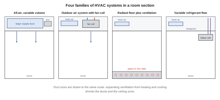
- All-air systems condition air in a central air handler and duct it to every room. A constant-volume system supplies a fixed airflow and varies its temperature; a variable-air-volume (VAV) system supplies air at a fixed cool temperature and varies the airflow to each zone with a box and damper, reheating where needed. All-air systems handle ventilation, cooling, humidity and filtration in one place, but they need large ducts, shafts and ceiling zones.
- Air-water systems separate the jobs. A dedicated outdoor air system (DOAS) supplies only the fresh air needed for ventilation, often through an energy recovery ventilator, while water or refrigerant carries most of the heating and cooling to terminal units in each room: fan coils, chilled beams, radiant ceilings or radiant floors. Ducts shrink to perhaps a third of an all-air system's.
- All-water systems heat with radiators, baseboard convectors or radiant floors supplied with hot water, with no ducts at all; ventilation then needs a separate system or operable windows.
- Refrigerant systems move heat directly with refrigerant pipes. Variable refrigerant flow (VRF) systems connect one outdoor unit to many indoor units, each with its own control, and can move heat from rooms that need cooling to rooms that need heating. Ductless split heat pumps are the small, residential version.
- Unitary systems package everything in one box: a rooftop unit on a store, a packaged terminal heat pump through the wall of a hotel room. They are cheap and simple but often noisy, inefficient and visible.
The air handler
In all-air and DOAS systems, the air handler is the plant. Air enters through an outdoor air intake and, in all-air systems, mixes with return air from the rooms; it passes through filters, a heat recovery wheel or plate, heating and cooling coils, sometimes a humidifier, and the supply fan, then leaves through the supply duct. A return or exhaust fan draws air back from the rooms and exhausts part of it outdoors. Air handlers are large: one serving the whole community hub would be about the size of a delivery van, and it needs a mechanical room with space to pull out its coils and filters, or a weatherproof roof enclosure.
Intakes and exhausts are visible architectural elements. Outdoor air intakes must be kept away from exhausts, loading docks, garbage rooms, parking entrances and other sources of contamination; codes and standards set minimum separations, typically about 3 to 10 m depending on the source. Exhausts from kitchens and laboratories go to the roof, away from intakes and windows. Intake louvres must be large enough to keep the air speed through them low, which keeps rain and snow out and reduces noise.
Air distribution
Ducts carry air from the air handler to the rooms. Main ducts are large and run through shafts and corridors; branch ducts are smaller and run above room ceilings to the diffusers. Air speed in the main ducts of a quiet building is typically about 5 to 7 m/s, lower near quiet rooms. The faster air moves, the smaller the duct, but the louder the system and the more energy the fan uses. Diffusers, grilles and slots release air into the room at a velocity and direction that mix it without uncomfortable air movement. Return air comes back through grilles, ducts or an open ceiling plenum.
The hall in the community hub shows why separating the jobs matters. Its peak sensible cooling load, from lesson 2, is about 37 kW, and it needs about 1,320 L/s of outdoor air for three hundred people. Joon-ho compares an all-air system that supplies all the cooling as cool air with a DOAS that supplies only the outdoor air, with the rest of the cooling carried by water to a radiant floor and fan coils.
# Air or water? Carrying the hall's cooling (studio values)
import math
Qs = 36900                 # peak sensible cooling load (W)
dT_air = 10            # supply air C below room temperature
oa = 1320                 # outdoor air needed for ventilation (L/s)
v_main = 6            # main duct velocity (m/s)

all_air = Qs / (1.2 * dT_air)                     # supply airflow for an all-air system
print(f"all-air supply flow {all_air:,.0f} L/s")
for name, flow in (("all-air", all_air), ("outdoor air only (DOAS)", oa)):
    area = flow / 1000 / v_main                     # duct cross-section (m2)
    d = math.sqrt(4 * area / math.pi) * 1000         # equivalent round duct diameter
    print(f"{name:24s} duct area {area:5.2f} m2, round duct about {d:4.0f} mm")

# the rest of the cooling carried by water at a 5-degree (C) rise
Q_water = Qs - 1.2 * oa * dT_air
gpm = Q_water / 4190 / 5
print(f"cooling left for water: {Q_water / 1000:.1f} kW, water flow {gpm:.2f} L/s")
pipe_d = math.sqrt(4 * gpm / 1000 / 1.2 / math.pi) * 1000
print(f"pipe at 1.2 m/s water speed: about {pipe_d:.1f} mm diameter")all-air supply flow 3,075 L/s all-air duct area 0.51 m2, round duct about 808 mm outdoor air only (DOAS) duct area 0.22 m2, round duct about 529 mm cooling left for water: 21.1 kW, water flow 1.01 L/s pipe at 1.2 m/s water speed: about 32.7 mm diameter
An all-air system needs about 3,100 L/s and a main duct about 810 mm in diameter, or an equivalent rectangular duct that would need a deep bulkhead or a ceiling zone of about a metre in the hall. The DOAS needs less than half that flow and a duct about 530 mm across. The cooling the DOAS does not supply is carried by water in a pipe about 35 mm in diameter. In a hall with an exposed timber roof structure, as Callum designed it, the smaller duct can run along the edge of the room above the stage instead of across the middle.
Fans use energy in proportion to the airflow times the pressure they work against, and the pressure rises steeply with velocity. Moving heat with water instead of air can cut the energy used for distribution by more than half. That is one reason energy codes limit fan power and why many high-performance buildings use DOAS with radiant or fan-coil systems.
Zoning and control
A zone is an area controlled by one thermostat. Rooms belong in the same zone only if they have similar loads at the same times: same orientation, similar use, similar hours. The hub needs separate zones for the hall, the library reading room, the daycare playrooms, the offices and the corridors, and the hall's west side may behave differently from its east. Too few zones leave some rooms too hot while others are too cold; too many add cost and complexity. Each home in the Riverlot building is at least one zone, with a thermostat that residents control.
Controls are where many systems fail in practice. A building automation system turns equipment on and off on schedules, resets supply temperatures with the weather, varies ventilation with occupancy and alarms faults. Architects should ask early how a system will be controlled and commissioned, lesson 12, and who will operate it. A simple system that the community hub's small maintenance staff can understand may perform better than a sophisticated one they cannot.
Systems for the Riverlot homes
Mensah sets out the options he considered for the sixty-five homes, each with its own effect on the architecture.
| Option | How it works | Effect on the architecture |
|---|---|---|
| Central heat pump plant, fan coil in each home, central ventilation | Heat pumps on the roof make hot and chilled water; pipes rise in a shaft to a fan coil above each home's bathroom or entry; a central energy recovery ventilator supplies the corridors and homes | Small pipe shafts; dropped ceilings in each entry; rooftop plant; large ventilation shafts |
| Variable refrigerant flow with an energy recovery ventilator in each home | One outdoor unit for several floors; refrigerant pipes to indoor units; each home ventilates itself through two wall openings | Refrigerant risers; small ceiling space; two vents per home on the facade |
| Heat pump in each home, ducted or ductless | A small outdoor unit per home on its balcony or the roof | Sixty-five outdoor units to place and screen; simple separate metering |
| Through-wall packaged units | One box per room through the exterior wall | Grilles in every facade; noise; poor efficiency in cold weather |
Each option is used in real buildings in Winnipeg. The choice depends on cost, energy, noise, maintenance and who pays the bills. Fan coils fed from a central plant are efficient and quiet but need careful metering if each household pays for its own heating. In-suite energy recovery ventilators give every home its own fresh air, which helps with odour transfer between homes and through corridors, a common complaint, but they put intake and exhaust openings on the facade that the architect must arrange. Individual heat pumps on balconies are simple but clutter the facade and take useful outdoor space.
Worked problem
Choosing the residential system
Riverlot wants low operating costs, quiet homes, simple metering and a facade free of clutter. Which option should the students recommend?
Show solution
- Through-wall packaged units fail on noise, efficiency and facade, so they are dropped first.
- Individual heat pumps on balconies give simple metering but sixty-five outdoor units on the facade and noise on every balcony; they conflict with the facade the students designed.
- Variable refrigerant flow with in-suite energy recovery ventilators gives individual control and fresh air directly to each home; the ventilator openings can be grouped with the window frames in a recess, as Joon-ho's facade allows. The refrigerant risers fit in the shafts beside the bathrooms.
- A central plant with fan coils is the most efficient and quietest, and needs only one rooftop plant, but each home needs an energy meter, and ventilation through corridors carries odours between homes unless each home has its own supply and exhaust.
- The students recommend the central heat pump plant with a fan coil in each home for heating and cooling, plus an energy recovery ventilator in each home with its openings set into the window recesses, and thermal energy meters for billing.
Answer: System choices balance efficiency, noise, metering, ventilation and facade; separating ventilation from heating and cooling gives the most flexibility.
Exercise 3: system comparison
This exercise takes one week.
- Choose two HVAC system families for the Foundry Collective's workshop floor of the Riverlot building.
- For each, draw a schematic section showing plant, ducts or pipes and terminals, with sizes estimated from the loads.
- Estimate the supply airflow, duct sizes and ceiling depth for each, and compare them with your floor-to-floor height.
- Recommend one system, giving reasons of space, energy, noise, cost and maintenance.
Self-critique checklist
- Have I separated ventilation from heating and cooling where it makes sense?
- Are my intakes far from exhausts and the loading area?
- Do zones group rooms with similar loads and hours?
- Can the operators understand and maintain the system?
Common mistakes
MistakeChoosing an all-air system without checking the duct sizes against the ceiling space.
InsteadCalculate airflows and duct sizes early and compare them with the section.
MistakePlacing outdoor air intakes beside exhausts or the loading area.
InsteadSeparate intakes from all contamination sources by the required distances.
MistakePutting rooms with different orientations and hours in one zone.
InsteadZone by orientation, use and schedule.
MistakeForgetting how ventilation reaches each home.
InsteadDecide early between central and in-suite ventilation, and plan its openings or shafts.
MistakeChoosing a system the building's staff cannot operate.
InsteadMatch complexity to the people who will run it.
Summary and key terms
- HVAC systems heat, cool, ventilate, control humidity, filter and exhaust.
- Air, water and refrigerant carry heat; water and refrigerant need far less space than air.
- The main families are all-air, air-water (DOAS with terminals), all-water, refrigerant and unitary systems.
- Separating ventilation from heating and cooling reduces duct sizes and fan energy.
- Zoning, controls and the building's operators decide how well a system performs.
- Air handler
- Central equipment that filters, heats, cools and moves air.
- VAV
- Variable air volume: a system that varies the airflow to each zone.
- DOAS
- Dedicated outdoor air system: supplies only ventilation air, often with energy recovery.
- Fan coil
- A terminal unit with a fan and a water coil that heats or cools a room.
- VRF
- Variable refrigerant flow: a heat pump system serving many indoor units through refrigerant pipes.
- Zone
- An area controlled by one thermostat.
Practice problems
Work each problem on paper first, then reveal the answer to check.
A room has a sensible cooling load of 6 kW. With supply air 10 K below room temperature, what airflow is needed?
Show answer
6,000 ÷ (1.2 × 10) = 500 L/s.
A duct carries 1,000 L/s at 5 m/s. What is its cross-sectional area?
Show answer
1.0 ÷ 5 = 0.2 m².
How much more heat does water carry than air per unit volume, roughly?
Show answer
About 3,500 times as much.
Name the four parts of a typical air handler between the intake and the supply duct.
Show answer
Filters, heat recovery, heating and cooling coils, and the supply fan.
Why should a kitchen exhaust not be near an outdoor air intake?
Show answer
Exhaust air would be drawn back into the building.
Lesson quiz · 5 questions
Score 60% or more to complete this lesson.
Create a free account to save your progress, take quizzes and earn a certificate.