
ARCH-310 · Lesson 8 of 12 · 21 min
Thermal bridges
Lavoie opens the eighth lesson with the thermal camera image of the school's studio building that Abernathy showed in the environmental systems course: blue walls striped with yellow at every floor line, orange frames around every window, a hot streak along the parapet. 'Last spring you learned what this picture means,' she says. 'This term you learn to put a number on it, and to draw details that make the stripes disappear.' She hands out a printed table from a thermal bridging guide, rows of junction details with a single number beside each, and asks Joon-ho to find the detail matching the studio building's floor line: a concrete slab running straight through the wall to support a brick veneer. Its number is many times larger than that of the same junction with a thermally broken support. 'That number,' Lavoie says, 'is why a wall drawn at one resistance performs at half of it.' Thermal bridges are the subject of this lesson: how to quantify them, which ones matter most, and how to design them out.
Three kinds of heat loss
The heat flowing through a real wall can be divided into three parts. The clear field is the wall as drawn on the typical section, including uniformly distributed bridges such as studs, girts and clips; its performance is expressed as a U-factor per unit area, calculated by the methods of Lesson 2. Linear thermal bridges are junctions that run along a line: slab edges, balconies, parapets, shelf angles, window perimeters, corners and the base of the wall. Their extra heat loss is expressed as a linear transmittance, called psi, per unit length of the junction per degree of temperature difference. Point thermal bridges are isolated penetrations such as a steel beam running through the wall to support a canopy, an anchor for a sign or a structural connection for a balcony; their extra heat loss is expressed as a point transmittance, called chi, per penetration per degree.
The equation adds the heat lost through the linear and point bridges, spread over the total wall area, to the clear field U-factor. The values of psi and chi come from detailed two- and three-dimensional heat flow simulations of each junction, validated by laboratory tests. The Building Envelope Thermal Bridging Guide, first published by BC Hydro in 2014 and updated since, catalogues hundreds of common Canadian details, and international standards describe how such values are calculated. Designers pick the closest detail from a catalogue, or commission a simulation for an unusual one.
The clear field method in practice
The calculation below applies the method to a six-storey concrete-framed residential building of the kind built in many Canadian and American cities, with steel stud backup walls insulated outside the sheathing on clips. It compares the walls of a building with typical details of the past generation, unbroken balcony slabs, slab edges supporting brick with no insulation, windows set outboard of the insulation and uninsulated parapets, with the same walls using improved details.
# Clear field method: overall U-factor of a mid-rise residential wall
clear_field_u = 0.28                  # wall with exterior insulation on clips (W/m2K)
# junction lengths per unit of wall area (m per m2)
lengths = {"slab edge": 0.17, "balcony": 0.17, "window perimeter": 0.8, "parapet": 0.05}
typical = {"slab edge": 0.4, "balcony": 0.9, "window perimeter": 0.3, "parapet": 0.7}
improved = {"slab edge": 0.15, "balcony": 0.25, "window perimeter": 0.05, "parapet": 0.2}
def overall(psi):
    extra = {k: psi[k] * lengths[k] for k in psi}
    return clear_field_u + sum(extra.values()), extra
for name, psi in (("typical details", typical), ("improved details", improved)):
    u, extra = overall(psi)
    print(f"{name}: overall U {u:.3f}, effective RSI {1 / u:.2f}")
    for k, v in extra.items():
        print(f"   {k:17s} adds {v:.3f}  ({100 * v / u:4.1f} of every 100 units of loss)")
print(f"clear field alone: U {clear_field_u}, RSI {1 / clear_field_u:.2f}")typical details: overall U 0.776, effective RSI 1.29 slab edge adds 0.068 ( 8.8 of every 100 units of loss) balcony adds 0.153 (19.7 of every 100 units of loss) window perimeter adds 0.240 (30.9 of every 100 units of loss) parapet adds 0.035 ( 4.5 of every 100 units of loss) improved details: overall U 0.398, effective RSI 2.51 slab edge adds 0.026 ( 6.4 of every 100 units of loss) balcony adds 0.043 (10.7 of every 100 units of loss) window perimeter adds 0.040 (10.1 of every 100 units of loss) parapet adds 0.010 ( 2.5 of every 100 units of loss) clear field alone: U 0.28, RSI 3.57
With typical details, the junctions more than double the heat loss of the clear field wall, and the wall that was designed at a respectable resistance performs at well under half of it. The window perimeters, which no one notices on the elevation, are the largest single item, because there is so much of them; the balconies, a small part of the façade, come next, losing more than half as much as the whole clear field. With improved details, the overall U-factor is much closer to that of the clear field, and the effective resistance nearly doubles without a millimetre of extra insulation. This is the central lesson of thermal bridging: in a well-insulated building, the details matter more than the thickness of insulation.
The bridges that matter most
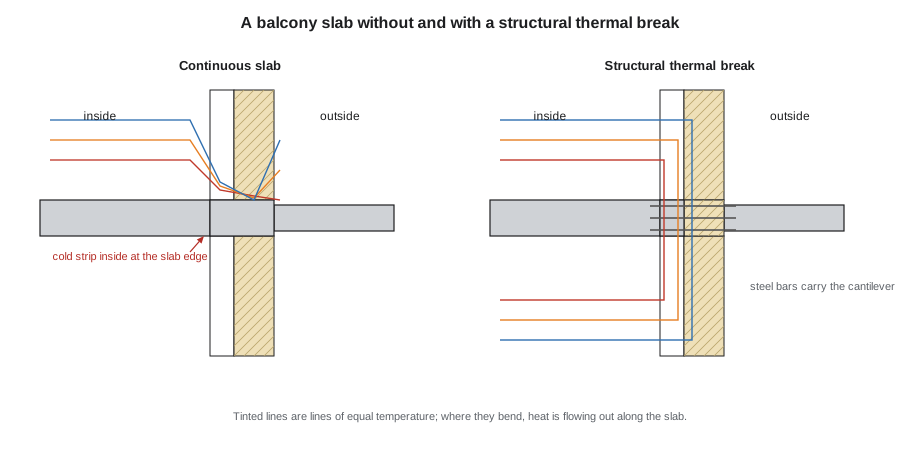
Some junctions recur on almost every building and dominate its thermal bridging. Balcony and canopy slabs that continue straight through the wall from the floor slab inside act as cooling fins, with psi values among the highest of any detail; they can be replaced by structurally independent balconies supported on their own columns or hung from the building with a few small connections, or interrupted by manufactured structural thermal breaks, assemblies of stainless steel bars and insulation that carry the cantilever moment across an insulated joint. Slab edges that support brick veneer through a steel shelf angle bolted tight to the slab bridge the insulation along every floor; stand-off shelf angles, held away from the slab by small brackets with the insulation running continuously behind them, cut the loss by more than half. Window perimeters lose heat where the frame meets the wall; setting windows in line with the insulation and insulating the rough opening reduce it greatly. Parapets of concrete or masonry, connected to the roof slab and uninsulated on top, conduct heat up into the cold air; wrapping them in insulation, or building them of light framing on top of the insulated roof, reduces this loss. Structural steel beams and columns passing through the envelope need thermally broken connections or, better, a design that keeps the structure inside.
Surface temperatures and comfort
Thermal bridges are not only an energy problem. They lower the inside surface temperature along the bridge, sometimes far below the rest of the wall, creating cold strips at floor lines and around windows where condensation and mould appear, especially behind furniture and curtains that trap cold air. On a Winnipeg winter night, the inside surface of a concrete slab edge that runs out to an unbroken balcony can drop below 10 °C, close to or below the dew point of moderately humid indoor air, while the wall a metre above it stays near room temperature. Occupants feel these cold surfaces as drafts and discomfort, and turn up the heat. The same temperature index used for windows in Lesson 7 can be calculated for any junction, and a target of about 70 or more, the same as for good windows, keeps most junctions free of condensation in a dry building.
Codes and practice
Energy codes in both countries were slow to address thermal bridging, but recent editions do. The National Energy Code for Buildings now requires major thermal bridges to be accounted for in its performance path and in some prescriptive provisions, and provincial and municipal programs such as the BC Energy Step Code and the Toronto Green Standard require overall wall performance to be calculated including linear and point bridges. Envelope consultants increasingly prepare a thermal bridging calculation for every project of significant size, and owners such as the City of Winnipeg ask for it in their standards. For the architect, the practical rule is to draw the insulation line continuously on every section and plan, as Lesson 1 asked, then to list every place where structure crosses it and choose a detail for each from a catalogue, with its psi value.
Designing out the bridges
The best thermal bridge is the one that never exists, because the structure was kept inside the insulation from the start. Form matters: a compact building with few projections, balconies that stand on their own structure or are recessed into the building as loggias, cladding supported by light clips rather than continuous slab edges, and parapets avoided or framed lightly. Where structure must cross the insulation, it should cross at few points with small cross-sections of low-conductivity materials, rather than along continuous lines. Stainless steel, which conducts heat about a third as well as carbon steel, is used for brick ties, clips and balcony connections for this reason; fibreglass and other composites do better still. Wood, which conducts heat about a tenth as well as concrete, makes timber buildings much more forgiving: the slab edges of a timber building bridge the insulation far less than those of a concrete building, though the steel connectors in mass timber need the same attention.
The architect also controls where the bridges fall relative to the rooms. A cold slab edge at the base of a floor-to-ceiling window is worse than one hidden behind a kitchen counter; a balcony connection in a bedroom is worse than one at a storage room. And where a bridge cannot be avoided, its effect on the interior can be reduced by insulating the inside surface along it, for example with a strip of insulation on the underside of the slab for the first 600 mm from the wall, a technique known as a wing insulation or an insulated soffit.
Worked problem
Balconies for Greenway Homes
Greenway Homes, the courtyard housing scheme from the housing studio, is a wood-frame building, but the client now asks whether its upper apartments can have balconies like those of a nearby concrete tower, cantilevered from the floor structure. What does thermal bridging suggest?
Show solution
- Cantilevering from wood floor joists through the wall is possible only for small balconies, and every joist that passes through the wall is a thermal and air leakage bridge, with a serious risk of water damage where the joists cross the envelope.
- A concrete-tower-style cantilevered slab is not available in wood frame and would, in any case, have a psi value among the highest of any detail.
- The best option is a self-supporting balcony structure, a light steel or timber frame standing on its own posts in the courtyard, tied back to the building at a few points with small, thermally broken connections through the wall.
- Alternatively, recess the balconies as loggias within the insulated volume of the building, with the floor of the loggia insulated beneath and waterproofed above as a small roof.
- Either way, the connections are counted as point bridges, with their chi values, in the wall's overall U-factor.
Answer: Self-supporting or recessed balconies avoid the long linear bridge of a cantilevered slab; the few remaining connections are small point bridges.
Exercise 8: thermal bridging calculation
This exercise takes about one week.
- Mark every junction where structure crosses the insulation on the plans, sections and elevations of your mixed-use building.
- Measure the lengths of each linear junction and count the point penetrations.
- Assign a psi or chi value to each from a published catalogue, and calculate the overall U-factor of each wall type by the clear field method.
- Redesign the three junctions that contribute the most heat loss and recalculate.
- Check the inside surface temperature of the worst remaining junction against the indoor dew point.
Common mistakes
MistakeReporting the clear field value as the wall's performance.
InsteadInclude linear and point thermal bridges by the clear field method.
MistakeCantilevering concrete balconies through the wall.
InsteadUse structural thermal breaks, self-supporting balconies or recessed loggias.
MistakeBolting shelf angles tight to the slab edge.
InsteadUse stand-off shelf angles with insulation running behind them.
MistakeIgnoring window perimeters.
InsteadSet windows in line with the insulation and insulate the rough openings; there is a great length of them.
MistakeAdding insulation thickness to make up for poor details.
InsteadFix the details first; they usually matter more.
Summary and key terms
- Wall heat loss has three parts: the clear field, linear bridges with psi values and point bridges with chi values.
- The clear field method adds the junction losses, spread over the wall area, to the clear field U-factor.
- Balconies, slab edges, shelf angles, window perimeters and parapets are the major bridges; typical details can more than double a wall's heat loss.
- Thermal bridges create cold inside surfaces where condensation and discomfort occur.
- Recent codes require bridges to be counted; good design keeps the structure inside the insulation and crosses it at few small points.
- Clear field
- The typical area of a wall, including uniformly distributed framing and fasteners.
- Linear transmittance
- The extra heat loss of a junction per unit length per degree; called psi.
- Point transmittance
- The extra heat loss of an isolated penetration per degree; called chi.
- Structural thermal break
- A manufactured assembly that carries structural loads across an insulated joint.
- Stand-off shelf angle
- A brick support held away from the slab edge so insulation can run behind it.
- Loggia
- A recessed balcony within the volume of the building.
- Clear field method
- A method that adds linear and point bridge losses to the clear field U-factor.
Practice problems
Work each problem on paper first, then reveal the answer to check.
Write the equation of the clear field method in words.
Show answer
Overall U equals the sum of psi times length plus chi times number, divided by the wall area, plus the clear field U.
In the calculation, which junction contributed most with typical details?
Show answer
The window perimeters, followed by the balconies.
Why do wood buildings suffer less from slab edge bridges than concrete buildings?
Show answer
Wood conducts heat about a tenth as well as concrete.
Name three ways to reduce the thermal bridge of a balcony.
Show answer
A structural thermal break, a self-supporting balcony on its own posts, or a recessed loggia.
Why are cold strips at slab edges a comfort and health problem as well as an energy one?
Show answer
Their inside surfaces can fall near the dew point, causing condensation and mould, and occupants feel them as drafts.
Lesson quiz · 5 questions
Score 60% or more to complete this lesson.
Create a free account to save your progress, take quizzes and earn a certificate.