
AERO-499 · Lesson 5 of 12 · 24 min
Preliminary design
Preliminary design turns the chosen concept into an aircraft with dimensions: a maximum take-off mass, a wing area and span, a motor rating, a battery energy, tail sizes and a layout drawing. It is where the requirements meet physics for the first time. In week 9 Owen and Lucas start the sizing loop that the concept review asked for, and they have promised to run it first with pessimistic assumptions. Arjun, who sized the Petrel 19 two years earlier, sits in on their first session. He warns them that the sizing of a battery-electric aircraft behaves differently from the fuel-burning aircraft in their textbooks, and that the difference is the whole story of electric flight.
Why the Breguet equation does not apply
For a fuel-burning aircraft, the Breguet range equation gives range in terms of the ratio of take-off to landing mass, because the aircraft gets lighter as it burns fuel and needs less lift, and so less power, as the flight goes on. A battery does not get lighter when it is discharged. The aircraft lands at its take-off mass, and the energy available per kilogram of battery is far less than the energy in a kilogram of fuel: about 0.2 kWh per kilogram for a complete aviation battery pack against about 12 kWh per kilogram for aviation fuel. Even allowing for the three times better efficiency of an electric drive than a small piston engine, the battery stores roughly twenty times less useful energy per kilogram.
For an electric aircraft in steady level flight, the energy needed per unit distance is the drag divided by the drive efficiency, and the drag is the weight divided by the lift-to-drag ratio. With a battery of mass \(m_b\) and usable specific energy \(e_b\), the range is
where \(\eta\) is the efficiency from the battery terminals to the air and \(m\) is the aircraft mass. The range depends linearly on the battery mass fraction, not on a logarithm of a mass ratio. Doubling the battery fraction doubles the range, but because the battery fraction cannot exceed one, there is a hard ceiling that no fuel-burning aircraft has. For the Plover E2, with a usable specific energy of 523 kJ/kg (200 Wh/kg in the pack, times the usable fractions described below), an overall efficiency of 0.75, a lift-to-drag ratio of 13.6 at the 80-knot normal cruise and a battery fraction of 0.39, the range to an empty battery is \(523{,}000 \times 0.75 \times 13.6 \times 0.39/9.81 \approx 212\) km. That is about 115 nautical miles, a fraction of the range of any piston trainer, and one reason the team defined the Plover E2 from the start as a circuit and air-work trainer, not a cross-country aircraft.
Usable energy
The battery's nameplate energy is not what the aircraft can use. Three factors reduce it. The state of charge window: lithium-ion cells age quickly if they are routinely charged to 100 per cent or discharged to zero, and the voltage at very low charge is too low for full power, so the team uses the window from 95 down to 5 per cent, 90 per cent of the nameplate. Ageing: R2 requires the mission at end of life, and the school's maintenance manager agreed that a pack will be replaced when its capacity falls to 85 per cent of new. Discharge losses: the cells' internal resistance turns some energy into heat, about 5 per cent at the currents of a lesson. Together these leave \(0.90 \times 0.85 \times 0.95 = 0.73\) of the nameplate energy for flying. Lucas says this single number is the one most often left out of student designs, and every point of it is worth several kilograms of aircraft.
The constraint diagram
Before the mass, the team fixes the two parameters that shape the aircraft: the wing loading (mass per unit wing area) and the power loading (shaft power per unit mass). Each performance requirement sets a boundary in the plane of these two parameters. The stall requirement sets a maximum wing loading, because for a given maximum lift coefficient a heavier wing loading means a higher stall speed. The take-off, climb and cruise requirements each set a minimum power for a given wing loading.
The other boundaries come from the familiar performance equations of earlier courses. Climb rate is the excess of power available over power required divided by weight. The take-off distance is the ground roll, from the acceleration that excess thrust gives, plus the air distance to clear the 15 m obstacle. Cruise needs power equal to drag times speed. Each is evaluated for the hot day in R3 and R4, and the cruise boundary assumes that maximum continuous power is 80 per cent of the five-minute take-off rating, which is typical for electric motors limited by winding temperature.
# Plover E2 constraint diagram: wing loading against shaft power-to-mass
import math
g = 9.81
CD0, AR, e = 0.030, 11.0, 0.80
K = 1 / (math.pi * e * AR)

def rho_at(h, dT=0.0):
    T0 = 288.15 - 0.0065 * h
    p = 101325 * (T0 / 288.15) ** 5.2559
    return p / (287.05 * (T0 + dT))

rho_hot = rho_at(400, 20)        # 400 m field elevation, ISA + 20 (hot summer day)

# 1. stall: Vs0 at or below 45 knots with full flap at sea level
CLmax, Vs = 1.90, 45 * 0.5144
WS_stall = 0.5 * 1.225 * Vs**2 * CLmax / g
print(f'stall limit: W/S <= {WS_stall:.1f} kg/m2')

def climb_rate(WS, PW, rho, V):
    q = 0.5 * rho * V**2
    CL = WS * g / q
    D_W = (CD0 + K * CL**2) / CL
    return 0.80 * PW / g - V * D_W               # m/s, propeller efficiency 0.80

def takeoff_dist(WS, PW, rho=rho_hot, mu=0.04, CLto=1.5, CLg=0.6):
    Vs_to = math.sqrt(2 * WS * g / (rho * CLto))
    Vlof, V2 = 1.1 * Vs_to, 1.2 * Vs_to
    V = 0.7 * Vlof                                # average point in the ground roll
    q = 0.5 * rho * V**2
    T_W = 0.60 * PW / (g * V)                     # static/low-speed propeller efficiency 0.60
    a = g * (T_W - mu - (q / (WS * g)) * (CD0 + 0.02 + K * CLg**2 - mu * CLg))
    if a <= 0: return float('inf')
    s_g = Vlof**2 / (2 * a)
    roc = climb_rate(WS, PW, rho, V2)
    if roc <= 0: return float('inf')
    gam = math.asin(min(roc / V2, 0.5))
    return s_g + 15 / math.tan(gam)               # to a 15 m (50 ft) height

def solve(f, target, lo=10, hi=400):
    for _ in range(60):
        mid = (lo + hi) / 2
        if f(mid) > target: lo = mid
        else: hi = mid
    return hi

def pw_takeoff(WS): return solve(lambda PW: takeoff_dist(WS, PW), 450.0)
def pw_climb(WS):
    V = math.sqrt(2 * WS * g / rho_hot * math.sqrt(K / (3 * CD0)))
    return solve(lambda PW: -climb_rate(WS, PW, rho_hot, V), -3.5)
def pw_cruise(WS, V=95 * 0.5144, h=900):          # 95 knots TAS at 900 m on continuous power
    rho = rho_at(h); q = 0.5 * rho * V**2
    return V * (q * CD0 / (WS * g) + K * WS * g / q) * g / 0.80 / 0.80   # continuous = 80 % of peak

print(f'\n{"W/S kg/m2":>10} {"take-off":>9} {"climb":>7} {"cruise":>7}   (peak shaft W/kg)')
for WS in range(35, 71, 5):
    print(f'{WS:10d} {pw_takeoff(WS):9.1f} {pw_climb(WS):7.1f} {pw_cruise(WS):7.1f}')
WS = 55.0
req = {'take-off 450 m to 15 m, hot day': pw_takeoff(WS), 'climb 3.5 m/s, hot day': pw_climb(WS), 'cruise 95 knots at 900 m': pw_cruise(WS)}
print(f'\ndesign point W/S = {WS:.0f} kg/m2')
for k, v in req.items(): print(f'  {k:34s} {v:6.1f} W/kg  -> {v*770/1000:5.1f} kW at 770 kg')
print('selected motor: 70 kW peak for 5 min, 56 kW continuous (91 W/kg peak at 770 kg)')stall limit: W/S <= 63.6 kg/m2
W/S kg/m2 take-off climb cruise (peak shaft W/kg)
35 41.5 61.5 94.7
40 46.3 62.7 84.7
45 51.3 63.9 77.2
50 56.4 65.1 71.3
55 61.6 66.2 66.7
60 66.9 67.2 63.1
65 72.3 68.2 60.1
70 77.8 69.1 57.7
design point W/S = 55 kg/m2
take-off 450 m to 15 m, hot day 61.6 W/kg -> 47.4 kW at 770 kg
climb 3.5 m/s, hot day 66.2 W/kg -> 50.9 kW at 770 kg
cruise 95 knots at 900 m 66.7 W/kg -> 51.4 kW at 770 kg
selected motor: 70 kW peak for 5 min, 56 kW continuous (91 W/kg peak at 770 kg)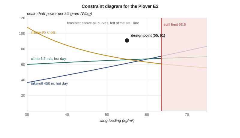
Three features of the diagram are typical of a light electric aircraft. First, the stall limit allows up to 63.6 kg/m² with a maximum lift coefficient of 1.9, but the team chooses 55, for two reasons: a lighter wing loading gives a lower stall speed, which the instructors value, and it leaves margin if the flap system does not reach 1.9. Second, the cruise boundary falls with wing loading, because a smaller wing has less friction drag; that is the reason a designer chasing efficiency pushes the wing loading up. Third, the take-off and climb boundaries are not the driving ones at the chosen wing loading; cruise and climb need about 66 W/kg, and the team selects a motor rated at 70 kW for five minutes and 56 kW continuous, about 91 W/kg at the final mass. The margin covers battery voltage sag late in a flight, propeller performance below the estimate and growth in mass.
The sizing loop
The mass of the aircraft depends on the battery, the battery depends on the energy for the mission, and the energy depends on the mass. The sizing loop solves this circular problem by iteration. The team starts with a guess of 800 kg, computes the power in each mission segment from the drag polar at that mass, adds up the energy, divides by the usable specific energy to get the battery mass, adds the payload and the empty mass without the battery, and compares the result with the guess. The empty mass without the battery comes from a fit to light aircraft and the electric trainers in the benchmark table: 205 kg plus 10 per cent of the take-off mass, covering the airframe, motor, inverter, propeller, avionics, interior and systems.
# Plover E2 sizing loop: mass build-up closed against mission energy
import math
g = 9.81
payload = 2 * 90 + 10            # two occupants and a bag, kg
e_pack = 200.0                   # pack-level specific energy at entry into service, Wh/kg
usable = 0.90                    # state of charge window used (95 % to 5 %)
eol = 0.85                       # capacity at end of life (pack replaced here)
eta_b = 0.95                     # battery discharge efficiency (internal resistance loss)
eta = 0.80 * 0.94                # propeller x (motor + inverter + cables)
WS, AR, CD0, e = 55.0, 11.0, 0.030, 0.80
K = 1 / (math.pi * e * AR)
rho_c = 1.125                    # 900 m standard day
V_c = 80 * 0.5144                # normal cruise 80 knots, m/s

def level_power(m, V, rho):
    S = m / WS
    CL = 2 * m * g / (rho * V**2 * S)
    D = 0.5 * rho * V**2 * S * (CD0 + K * CL**2)
    return D * V / eta / 1000          # battery-side kW

def mission_energy(m):
    p_cruise = level_power(m, V_c, rho_c)
    p_climb = p_cruise + m * g * 3.5 / eta / 1000      # climb at 3.5 m/s
    seg = [('taxi and run-up', 8 / 60, 4.0),
           ('take-off and climb', 6 / 60, p_climb),
           ('lesson (air work and circuits)', 34 / 60, 1.15 * p_cruise),
           ('descent and landing', 5 / 60, 0.45 * p_cruise),
           ('reserve, 30 min at normal cruise', 30 / 60, p_cruise)]
    return seg, sum(t * p for _, t, p in seg)

def empty_no_batt(m):
    return 0.10 * m + 205.0                # airframe, systems, motor, avionics (fit)

m = 800.0
for it in range(1, 30):
    seg, E = mission_energy(m)
    m_batt = E * 1000 / (e_pack * usable * eol * eta_b)
    m_new = payload + m_batt + empty_no_batt(m)
    if it <= 4 or abs(m_new - m) < 0.05:
        print(f'iteration {it:2d}: mass {m:7.1f} kg  mission energy {E:5.1f} kWh  battery {m_batt:5.1f} kg  new mass {m_new:7.1f} kg')
    if abs(m_new - m) < 0.05: break
    m = m_new
print()
for name, t, p in seg: print(f'{name:34s} {t*60:4.0f} min {p:6.1f} kW {t*p:6.2f} kWh')
print(f'\nMTOW {m:.0f} kg, wing area {m/WS:.2f} m2, span {math.sqrt(AR*m/WS):.2f} m')
print(f'battery {m_batt:.0f} kg = {m_batt/m*100:.1f} % of MTOW, nameplate {m_batt*e_pack/1000:.1f} kWh')
print(f'empty mass with battery {empty_no_batt(m)+m_batt:.0f} kg')
for ep in (180, 200, 220, 250):
    mm = 800.0
    for _ in range(60):
        _, E = mission_energy(mm); mb = E * 1000 / (ep * usable * eol * eta_b); mm = payload + mb + empty_no_batt(mm)
print(f'pack {ep} Wh/kg -> MTOW {mm:6.0f} kg, battery {mb:5.0f} kg')iteration 1: mass 800.0 kg mission energy 44.9 kWh battery 308.6 kg new mass 783.6 kg iteration 2: mass 783.6 kg mission energy 43.9 kWh battery 302.3 kg new mass 775.7 kg iteration 3: mass 775.7 kg mission energy 43.5 kWh battery 299.3 kg new mass 771.9 kg iteration 4: mass 771.9 kg mission energy 43.3 kWh battery 297.9 kg new mass 770.1 kg iteration 9: mass 768.5 kg mission energy 43.1 kWh battery 296.6 kg new mass 768.4 kg taxi and run-up 8 min 4.0 kW 0.53 kWh take-off and climb 6 min 65.4 kW 6.54 kWh lesson (air work and circuits) 34 min 34.8 kW 19.75 kWh descent and landing 5 min 13.6 kW 1.14 kWh reserve, 30 min at normal cruise 30 min 30.3 kW 15.15 kWh MTOW 768 kg, wing area 13.97 m2, span 12.40 m battery 297 kg = 38.6 % of MTOW, nameplate 59.3 kWh empty mass with battery 578 kg pack 180 Wh/kg -> MTOW 838 kg, battery 359 kg pack 200 Wh/kg -> MTOW 768 kg, battery 297 kg pack 220 Wh/kg -> MTOW 720 kg, battery 253 kg pack 250 Wh/kg -> MTOW 669 kg, battery 207 kg
The loop converges in nine iterations to 768 kg, which the team rounds up to a design maximum take-off mass of 770 kg . The battery is 297 kg, 39 per cent of the take-off mass, with a nameplate energy of 59 kWh. More than a third of the mission energy goes into the reserve, which is never used on a normal lesson. The take-off and climb take only 6 minutes but use 15 per cent of the energy, because they need almost twice the power of the lesson segments.
The sensitivity at the end of the output is the result the team takes to the sponsor in week 10. With pessimistic cells, 180 Wh/kg at pack level, the aircraft grows to 838 kg. With 220 Wh/kg it shrinks to 720 kg, and with 250 Wh/kg, a value some suppliers project for the end of the decade, to 669 kg. The design closes in every case, at a mass similar to a two-seat piston trainer, and Dr. Nakamura accepts the result as the answer to the first big question: a battery-electric trainer for this mission is physically possible. Whether it is worth building is a question for later lessons.
Arjun points out what the sensitivity also shows. Each 10 Wh/kg of specific energy is worth roughly 25 kg of take-off mass near the design point, and a heavier aircraft needs more energy, a bigger wing and a bigger motor, so the effect compounds. The team therefore makes the pack specific energy a tracked parameter, reviewed at every design review, and specifies the pack by its end-of-life usable energy, not its nameplate.
Configuration and layout
With the main parameters fixed, the team draws the aircraft. The wing area is \(770/55 = 14.0\) m². The aspect ratio is a trade between induced drag, which favours a long span, and wing mass and hangar width, which favour a short one. The team chooses 11, giving a span of 12.4 m , which fits the school's hangar doors with half a metre to spare on each side. A taper ratio of 0.6 gives a root chord of 1.40 m, a tip chord of 0.84 m and a mean aerodynamic chord of 1.13 m. The aerofoil is a 15 per cent thick natural laminar flow section, chosen for low drag in cruise and docile stall behaviour; its laminar flow will be partly lost to insects and rain, so the drag estimates assume transition well forward.
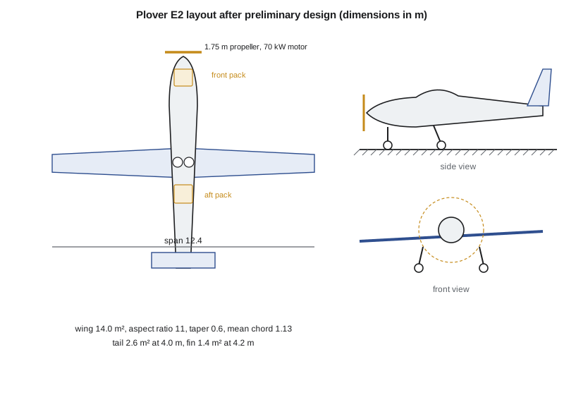
The tail is sized by volume coefficients, the ratio of tail area times arm to wing area times chord (or span, for the fin), taken from similar light aircraft. A horizontal tail of 2.6 m² at an arm of 4.0 m gives a volume coefficient of 0.66, on the high side for a trainer because it must trim the aircraft with full flap at the forward centre of gravity in the landing flare. A fin of 1.4 m² at 4.2 m gives a vertical tail volume of 0.034, which the spin requirement may push up later; spin recovery depends strongly on how much of the rudder is shielded by the horizontal tail.
The battery is split into two packs of 29.6 kWh and about 150 kg each, one ahead of the cabin behind a firewall and one behind the seats, so that their masses balance about the wing and either pack alone can power the motor in an emergency. Each pack holds 108 series groups of 15 cylindrical cells, 1,620 cells per pack, and with both packs connected in parallel the aircraft's bus has 108 series groups of 30 cells, about 394 V nominal. Each pack has its own battery management system, contactors, fuse and liquid cooling loop. The propeller is a three-blade, ground-adjustable composite unit of 1.75 m diameter, turning at up to 2,400 rpm; its helical tip Mach number in cruise on a hot day is about 0.64, low enough to keep noise down, which the neighbours of St. Andrews will appreciate.
The undercarriage is fixed tricycle, with the main wheels 20 per cent of the mean chord behind the aft centre-of-gravity limit, so the aircraft cannot tip onto its tail with a heavy instructor in the back of the loading range, and with spring-steel main legs that absorb the hard landings students make.
The preliminary design review
The preliminary design review in week 16 is the second formal review. The board checks that the design meets every requirement on paper, that the analyses behind it are sound and reviewed, and that the risks are understood. The analyses that support it, aerodynamics, performance, stability, battery behaviour and structure, are the subject of the next two lessons. The team presents the sizing results, the constraint diagram and the layout here, and the board approves the design for detailed work with one action: confirm, by test, the pack-level specific energy the sizing assumes.
Worked problem
Range from the battery fraction
An electric aircraft has a battery fraction of 0.35, a usable specific energy of 150 Wh/kg, a drive efficiency of 0.75 and a lift-to-drag ratio of 14. Estimate its range to an empty battery.
Show solution
- Convert the specific energy: \(150 \times 3600 = 540{,}000\) J/kg.
- \(R = 540{,}000 \times 0.75 \times 14 \times 0.35/9.81\).
- \(R = 202{,}000\) m, about 200 km.
Answer: About 200 km. Doubling the battery fraction would double it, but the fraction cannot exceed one, so electric range has a hard ceiling.
Common mistakes
MistakeUsing the Breguet equation for a battery aircraft.
InsteadUse the linear relation between range and battery fraction; the aircraft does not get lighter.
MistakeSizing with the nameplate battery energy.
InsteadApply the state of charge window, the end-of-life capacity and the discharge losses.
MistakeChoosing the wing loading at the stall limit.
InsteadLeave margin for flap performance and the instructors' preference for a low stall speed.
MistakeTreating the sizing result as fixed.
InsteadTrack the battery specific energy as a design parameter and review it at every design review.
Summary and key terms
- A battery-electric aircraft lands at its take-off mass, so range grows linearly with battery mass fraction and has a hard ceiling.
- Usable energy is the nameplate value times the state of charge window, end-of-life capacity and discharge efficiency, 0.73 for the Plover E2.
- The constraint diagram sets the wing loading at 55 kg/m², below the 63.6 kg/m² stall limit, and the motor at 70 kW peak, 56 kW continuous.
- The sizing loop converges at 770 kg with a 297 kg, 59 kWh battery; each 10 Wh/kg of pack specific energy is worth about 25 kg.
- The layout has a 14.0 m², 12.4 m wing, two balanced battery packs and a conventional tail sized by volume coefficients.
- Wing loading
- Aircraft mass divided by wing area.
- Power loading
- Shaft power per unit aircraft mass.
- Constraint diagram
- Plot of requirement boundaries in the wing loading and power loading plane.
- Sizing loop
- Iteration of mass and mission energy until they agree.
- Battery mass fraction
- Battery mass divided by take-off mass.
- Tail volume coefficient
- Tail area times arm divided by wing area times chord or span.
Practice problems
Work each problem on paper first, then reveal the answer to check.
Why does a battery aircraft not benefit from the Breguet logarithm?
Show answer
Its mass does not fall during the flight.
What fraction of nameplate energy can the Plover E2 use at end of life?
Show answer
\(0.90 \times 0.85 \times 0.95 = 0.73\).
What sets the maximum wing loading?
Show answer
The stall speed requirement with the maximum lift coefficient of the flap system.
How much of the mission energy goes to the reserve?
Show answer
About 15 of 43 kWh, more than a third.
Why are there two battery packs?
Show answer
They balance about the wing, and either can power the motor if the other is lost.
Lesson quiz · 5 questions
Score 60% or more to complete this lesson.
Create a free account to save your progress, take quizzes and earn a certificate.