
AERO-450 · Lesson 4 of 12 · 26 min
Hover and forward flight
Sam Littlechild flew air ambulances for eight years before joining Borealis Aerospace as a test pilot, and he asks Arjun to explain something he learned by feel. On every take-off from a hospital pad, there is a moment, at about 15 to 20 knots, when the helicopter shudders briefly and then suddenly climbs better with the same power. Pilots call it translational lift. At the other end of the speed range, the medevac twin's never-exceed speed is about 155 knots, and above that the cyclic stick runs out of authority and the vibration rises. Both effects come from the way a rotor behaves when it moves edgewise through the air, which is the subject of this lesson.
Hover: the rotor at rest
In hover the flow through the rotor is axially symmetric. Every blade sees the same velocity at the same radius whatever its azimuth, so the forces are steady in the rotating frame, the thrust is vertical, and the analysis of lessons 2 and 3 applies. The pilot holds position with small cyclic inputs that tilt the thrust, and with pedals that balance torque. Hovering in ground effect, within about one rotor diameter of the ground, takes less power because the ground blocks the wake and slows the induced flow; lesson 6 quantifies this. Hovering out of ground effect, above about one diameter, is the most demanding steady condition in terms of power. It is also the condition in which the wake recirculates most easily near obstacles and the pilot's workload is high, especially in gusty wind near buildings.
Advance ratio and the asymmetry of forward flight
In forward flight at speed \(V\), the rotor disk is tilted slightly forward, and the air approaches it nearly edgewise. The key parameter is the advance ratio, the forward speed component in the plane of the disk divided by the tip speed:
where \(\alpha_D\) is the disk angle of attack, a few degrees nose-down in cruise. Measuring the blade azimuth \(\psi\) from the tail in the direction of rotation, the tangential velocity at nondimensional radius \(r\) is
At \(\psi = 90^{\circ}\) the blade advances into the wind and its speed adds to the flight speed; at \(\psi = 270^{\circ}\) it retreats and the speeds subtract. At 70 m/s (136 knots) and 210 m/s tip speed, \(\mu = 0.33\): the advancing tip moves at 280 m/s, the retreating tip at 140 m/s, and the dynamic pressure differs by a factor of four. If every blade kept the same pitch, the advancing side would produce far more lift than the retreating side and the helicopter would roll over. This dissymmetry of lift is the central problem of forward flight. It is solved, as lesson 5 explains, by letting the blades flap and by cyclic pitch, which reduces pitch on the advancing side and increases it on the retreating side.
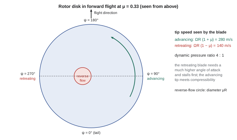
On the retreating side the tangential velocity becomes negative where \(r < -\mu\sin\psi\). The air there flows from the trailing edge to the leading edge. This reverse-flow region is a circle of diameter \(\mu R\) touching the hub on the retreating side: at \(\mu = 0.33\) it reaches 1.8 m out along the 5.5 m blade. Because the dynamic pressure there is small, the effect on lift is modest at helicopter speeds, but it becomes important for slowed-rotor compounds at advance ratios above 0.5.
Glauert's induced velocity
Momentum theory for forward flight was proposed by Hermann Glauert in 1926 by analogy with a wing. The mass flow through the disk is taken as \(\rho A U\), where \(U\) is the total velocity at the disk, combining the freestream and the induced velocity. With \(T = 2\dot m v_i\) as in hover, the induced velocity satisfies
The second form is the nondimensional version, with \(\lambda\) the total inflow ratio through the disk. It cannot be solved explicitly, so the code uses Newton iteration. Glauert's formula reduces correctly to momentum theory in hover and to the result for a wing of span \(2R\) at high speed, where \(v_i \approx T/(2\rho A V)\). It cannot be derived rigorously, but it agrees well with measurements and is used throughout rotorcraft performance work.
# Forward flight: advance ratio, Glauert induced velocity, and where the retreating blade sees reverse flow.
import math
rho, R, VT, m = 1.225, 5.5, 210.0, 3000.0
A = math.pi * R**2; W = m * 9.81
CT = W / (rho * A * VT**2)
lam_h = math.sqrt(CT / 2)                      # hover inflow ratio
def glauert(mu, alpha_deg):
    """Solve lambda = mu tan(alpha) + C_T / (2 sqrt(mu^2 + lambda^2)) by Newton iteration."""
    t = math.tan(math.radians(alpha_deg)); lam = lam_h
    for _ in range(50):
        f = lam - mu * t - CT / (2 * math.sqrt(mu**2 + lam**2))
        df = 1 + CT / 2 * lam / (mu**2 + lam**2) ** 1.5
        lam -= f / df
    return lam, lam - mu * t                    # total inflow, induced part
print(f"C_T = {CT:.5f}, hover inflow lambda_h = {lam_h:.4f}, v_h = {lam_h*VT:.2f} m/s")
print()
print(" V (m/s)  V (kt)    mu    lambda_i/lambda_h   v_i (m/s)   high-speed approx   adv. tip Mach  reverse-flow circle")
for V in (0, 10, 20, 30, 40, 50, 60, 70, 80):
    mu = V / VT                                 # small shaft tilt: mu ~ V / (Omega R)
    alpha = -0.08 * V                           # disk tilts forward about 0.08 deg per m/s (illustrative)
    lam, lami = glauert(mu, alpha)
    approx = f"{CT / (2 * mu) / lam_h:7.3f}" if mu > 0 else "    --"
    Mtip = (VT + V) / 340.3
    print(f"  {V:5.0f}   {V*1.9438:6.0f}   {mu:5.3f}      {lami/lam_h:6.3f}          {lami*VT:6.2f}       "
          f"{approx:>7s}           {Mtip:5.3f}      {mu*R:5.2f} m")
print()
for V in (70.0, 80.0):
    mu = V / VT
    # retreating blade (psi = 270 deg): U_T = Omega R (r - mu); the tip still sees Omega R (1 - mu)
print(f"At {V:.0f} m/s the retreating tip sees {VT*(1-mu):.0f} m/s against {VT*(1+mu):.0f} m/s on the advancing tip, a dynamic pressure ratio of {((1-mu)/(1+mu))**2:.2f}")C_T = 0.00573, hover inflow lambda_h = 0.0535, v_h = 11.24 m/s
V (m/s) V (kt) mu lambda_i/lambda_h v_i (m/s) high-speed approx adv. tip Mach reverse-flow circle
0 0 0.000 1.000 11.24 -- 0.617 0.00 m
10 19 0.048 0.828 9.31 1.124 0.646 0.26 m
20 39 0.095 0.542 6.09 0.562 0.676 0.52 m
30 58 0.143 0.373 4.19 0.375 0.705 0.79 m
40 78 0.190 0.281 3.16 0.281 0.735 1.05 m
50 97 0.238 0.225 2.53 0.225 0.764 1.31 m
60 117 0.286 0.187 2.10 0.187 0.793 1.57 m
70 136 0.333 0.160 1.80 0.161 0.823 1.83 m
80 156 0.381 0.140 1.57 0.141 0.852 2.10 m
At 70 m/s the retreating tip sees 140 m/s against 280 m/s on the advancing tip, a dynamic pressure ratio of 0.25
At 80 m/s the retreating tip sees 130 m/s against 290 m/s on the advancing tip, a dynamic pressure ratio of 0.20The output shows how quickly induced velocity falls with speed. At 20 m/s (39 knots) it is already 54 per cent of the hover value, and above about 30 m/s the high-speed approximation \(v_i \approx T/(2\rho A V)\), shown in the next column as a ratio to the hover value, matches the full solution to better than 1 per cent. The advancing tip Mach number rises from 0.62 in hover to 0.85 at 80 m/s.
Translational lift
Translational lift, the effect Sam described, follows directly from these numbers. As the helicopter accelerates from hover, the rotor moves into fresh air rather than working on its own recirculating wake, the mass flow through the disk rises, and the induced velocity needed for the same thrust falls. Between hover and 20 m/s the induced power falls by almost half. At 10 to 20 knots the rotor flies through its own tip vortices, especially at the front of the disk where the wake from the advancing blades is swept back; this gives the brief shudder, known as transverse flow effect, and a roll tendency the pilot corrects with cyclic. Once through it, at about 15 to 25 knots for a helicopter of this size, the aircraft has effective translational lift: the power required drops sharply and the rotor gives more thrust for the same power. Air ambulance take-off profiles use this, accelerating near the ground to gain effective translational lift before climbing. When an obstacle prevents that, the pilot must climb vertically out of ground effect, which needs the most power of any manoeuvre. Lesson 6 shows the effect on the power curve and the helicopter's hover and take-off performance charts.
What limits forward speed
Three effects limit a conventional helicopter's speed. The first is retreating blade stall. To keep lift balanced, the retreating blade must work at a high angle of attack, highest near its tip at about \(\psi = 270^{\circ}\), where the dynamic pressure is lowest. As speed rises, that angle exceeds the section's stall angle. The onset is gradual: vibration rises, control loads increase, and the helicopter tends to pitch nose-up and roll toward the retreating side. Stall is worse at high weight, high density altitude, and in turns, because all three raise \(C_T/\sigma\). The rotor's limits are often plotted as maximum \(C_T/\sigma\) against advance ratio, with a boundary that falls from about 0.12 near hover to under 0.08 at \(\mu = 0.4\).
The second is compressibility on the advancing blade. When the advancing tip Mach number exceeds about 0.9, shock waves form on the tip, drag and power rise steeply, and impulsive noise increases. That limits the combination of tip speed and flight speed: at a tip speed of 210 m/s and sea-level temperature, the advancing tip reaches Mach 0.9 at about 96 m/s. Designers choose the tip speed as a compromise, low enough to keep the advancing tip subsonic at the design speed and the noise acceptable, but high enough to keep the retreating blade from stalling and to store enough kinetic energy for autorotation.
The third is power. Parasite drag grows as the cube of speed in power terms and eventually uses all the engine power available. For the medevac twin, lesson 6 finds this power limit near 150 knots, close to its never-exceed speed. In practice, manufacturers set the never-exceed speed with a margin to the first two limits as well and reduce it at high altitude and weight, where the rotor is more heavily loaded.
| Limit | Physical cause | Symptoms | Mitigations |
|---|---|---|---|
| Retreating blade stall | High angle of attack on the retreating side at low dynamic pressure | Vibration, nose-up pitch, roll toward the retreating side | Reduce speed, weight or load factor; high-lift outboard airfoils |
| Advancing tip compressibility | Tip Mach number near 0.9 | Power rise, noise, control loads | Thin swept tips; lower tip speed |
| Power available | Parasite power rising as speed cubed | No acceleration | Clean airframe, retractable gear, more power |
| Reverse flow | Negative tangential velocity on the retreating side | Little at \(\mu < 0.4\) | Matters for slowed-rotor compounds |
Trim in forward flight
To fly level at constant speed, the rotor thrust must balance the weight and the fuselage drag, and the moments about the centre of gravity must balance. The rotor tilts forward so that the horizontal component of thrust overcomes drag; at 70 m/s with a parasite drag area of 1.3 m² the drag is about 3.9 kN, so the disk tilts about \(\arctan(3.9/29.4) = 7.6^{\circ}\) forward. The fuselage hangs below the rotor and pitches nose-down to match, which is why helicopters cruise noticeably nose-down. The tail rotor must still balance torque, and its thrust also creates a small sideways force that the pilot balances by tilting the main rotor slightly, so many single-rotor helicopters hover with one skid low. A trim calculation solves for the collective, two cyclic angles, the tail rotor pitch and the fuselage attitudes together, and it is the starting point for performance, loads and handling-qualities work.
Worked problem
Advance ratio at cruise
The medevac twin cruises at 130 knots at sea level. Find the advance ratio and the advancing and retreating tip speeds.
Show solution
- \(V = 130 \times 0.5144 = 66.9\ \mathrm{m/s}\).
- \(\mu = 66.9/210 = 0.319\).
- Advancing tip \(210 + 66.9 = 277\ \mathrm{m/s}\); retreating tip \(210 - 66.9 = 143\ \mathrm{m/s}\).
Answer: \(\mu = 0.32\); the tips see 277 and 143 m/s, a dynamic pressure ratio of 3.8.
Worked problem
High-speed induced velocity
Use \(v_i \approx T/(2\rho A V)\) to estimate the induced velocity and induced power of the medevac twin at 60 m/s, and compare with the code.
Show solution
- \(v_i = 29\,430/(2 \times 1.225 \times 95.03 \times 60) = 2.11\ \mathrm{m/s}\).
- Ideal induced power \(T v_i = 29\,430 \times 2.11 = 62\ \mathrm{kW}\).
Answer: 2.11 m/s against 2.10 m/s from the full solution; induced power has fallen from 331 kW in hover to about 62 kW.
Worked problem
Advancing tip Mach limit on a hot day
On a 30 °C day at sea level the speed of sound is about 349 m/s. At what flight speed does the medevac twin's advancing tip reach Mach 0.9?
Show solution
- Advancing tip speed \(= 0.9 \times\) speed of sound.
- \(V = 0.9a - 210\).
Answer: About 104 m/s (202 knots), well above the never-exceed speed. The speed of sound rises with temperature, so hot days relieve compressibility slightly, while cold days, common in Winnipeg winters, make it worse.
Common mistakes
MistakeTranslational lift appears because the rotor speeds up in forward flight.
InsteadThe rotor speed stays constant; the rotor works on more fresh air, so less induced velocity is needed for the same thrust.
MistakeThe advancing blade stalls first because it carries more lift.
InsteadThe retreating blade stalls first: it needs a high angle of attack to make lift at low dynamic pressure.
MistakeRaising tip speed is a free way to delay retreating blade stall.
InsteadIt also raises the advancing tip Mach number, noise and profile power.
MistakeReverse flow limits every helicopter's top speed.
InsteadAt conventional advance ratios the reverse-flow region has little dynamic pressure; it matters mainly for slowed-rotor compounds.
Summary and key terms
- Hover is axisymmetric; forward flight is not.
- The advance ratio, flight speed over tip speed, measures the asymmetry: the advancing blade sees \(\Omega R(1 + \mu)\) at the tip and the retreating blade \(\Omega R(1 - \mu)\).
- The dissymmetry of lift is removed by flapping and cyclic pitch.
- Glauert's formula gives the induced velocity in forward flight, which falls quickly with speed and approaches \(T/(2\rho A V)\).
- Translational lift is the drop in power as the rotor moves into fresh air at 15 to 25 knots.
- Top speed is limited by retreating blade stall, advancing tip compressibility near Mach 0.9 and the power needed to overcome parasite drag.
- In level flight the rotor tilts forward to balance drag.
- Advance ratio
- \(\mu = V\cos\alpha_D/(\Omega R)\).
- Azimuth angle
- Blade position around the disk, measured from the tail in the direction of rotation.
- Dissymmetry of lift
- Unequal lift on the advancing and retreating sides at equal pitch.
- Reverse-flow region
- Part of the retreating side where air flows from trailing edge to leading edge.
- Glauert formula
- Momentum-theory relation for induced velocity in forward flight.
- Translational lift
- The increase in rotor efficiency as the aircraft moves into undisturbed air.
- Retreating blade stall
- Stall of the retreating blade at high speed or loading.
- Trim
- Control and attitude settings that give steady, balanced flight.
Practice problems
Work each problem on paper first, then reveal the answer to check.
What is the diameter of the reverse-flow circle at \(\mu = 0.25\) for \(R = 5.5\ \mathrm{m}\)?
Show answer
\(\mu R = 1.375\ \mathrm{m}\).
Why does the induced velocity fall with forward speed?
Show answer
The mass flow through the disk grows with speed, so less velocity increment is needed for the same thrust.
At what flight speed does the medevac twin's advancing tip reach Mach 0.9 at ISA sea level?
Show answer
\(0.9 \times 340.3 - 210 = 96\ \mathrm{m/s}\), about 187 knots.
Which three conditions make retreating blade stall worse?
Show answer
High weight, high density altitude and turns or pull-ups (higher load factor).
How much does the rotor tilt forward at 70 m/s for 3.9 kN of drag and 29.4 kN of weight?
Show answer
About 7.6 degrees.
Lesson quiz · 5 questions
Score 60% or more to complete this lesson.
Create a free account to save your progress, take quizzes and earn a certificate.