
AERO-450 · Lesson 3 of 12 · 25 min
Blade element theory
Momentum theory told Arjun how much power the medevac twin's rotor needs at best, but it says nothing about the blades. Tamarack Air Medical is considering replacement main rotor blades from a supplier that offers a different twist, and the operator wants to know whether the new blades would help on hot days. To answer, Arjun needs a model that starts from the airfoil sections along each blade. Blade element theory does that: it divides each blade into many short spanwise strips, finds the velocity and angle of attack each strip sees, uses two-dimensional airfoil data to get its lift and drag, and integrates along the span and around the rotor.
The blade element
Consider a strip of blade of width \(dr\) at radius \(r\), with chord \(c\) and pitch angle \(\theta\) measured from the plane of rotation. In hover the strip moves through the air at the tangential velocity \(U_T = \Omega r\). Air also flows down through the disk at the inflow velocity \(U_P\), which in hover is the induced velocity \(v_i\) and in climb is \(V_c + v_i\). The resultant velocity \(U\) is inclined below the plane of rotation by the inflow angle \(\phi = \arctan(U_P/U_T)\), so the angle of attack of the section is
The small-angle form holds well over most of a helicopter blade, where the inflow angle is a few degrees. Near the root, where \(\Omega r\) is small, it does not, but that region produces little thrust.
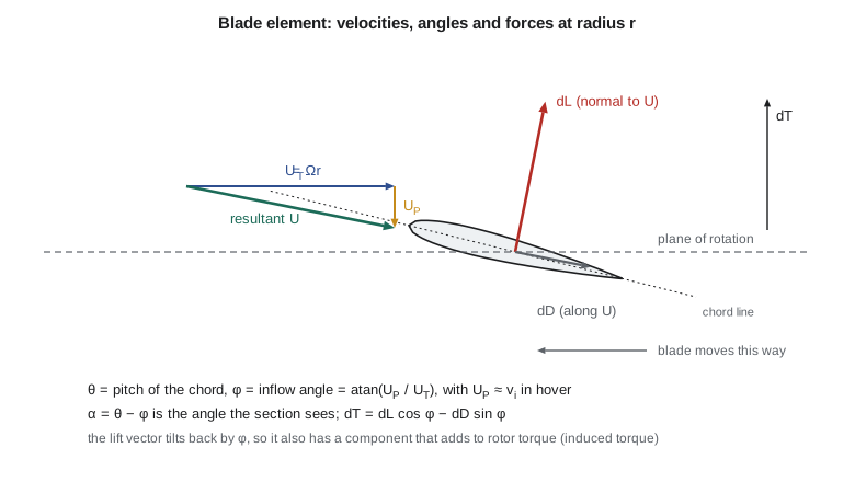
The lift and drag per unit span are \(dL = \tfrac{1}{2}\rho U^{2} c\,c_l\,dr\) and \(dD = \tfrac{1}{2}\rho U^{2} c\,c_d\,dr\), with \(c_l = a\alpha\) for an unstalled section with lift-curve slope \(a\) (about \(2\pi\) per radian in theory, nearer 5.7 per radian for a real section). Because lift is perpendicular to the local resultant velocity, resolving the forces normal to and in the plane of rotation gives
The term \(\phi\,dL\) is the induced torque: the backward tilt of the lift vector, caused by the inflow, is what costs induced power. The term \(dD\) is profile torque. Summing over \(N_b\) blades and integrating from the root cut-out to the tip, and writing the result in coefficient form with \(r\) now meaning the nondimensional radius \(r/R\) and \(\lambda = U_P/(\Omega R)\) the inflow ratio, gives
Here \(\sigma = N_b c/(\pi R)\) is the rotor solidity, the fraction of the disk area covered by blades. For the medevac twin, four blades of 0.32 m chord on a 5.5 m radius give \(\sigma = 0.074\), typical of helicopters (0.05 to 0.10).
Simple closed-form results
With uniform inflow and constant pitch, the integrals are easy. For an untwisted blade with no root cut-out and no tip losses, \(C_T = (\sigma a/2)(\theta/3 - \lambda/2)\). For a linearly twisted blade, \(\theta(r) = \theta_0 + \theta_{tw} r\), the thrust is the same as that of an untwisted blade with the pitch it has at three-quarters radius:
That is why rotor pitch is usually quoted at 75 per cent radius. With constant profile drag coefficient \(c_{d0}\) the power splits neatly into induced and profile parts:
The induced power factor \(\kappa\), typically 1.1 to 1.2, accounts for nonuniform inflow and tip losses; momentum theory alone gives \(\kappa = 1\). This simple formula is one of the most useful in rotor design. It shows that profile power grows with solidity and drag coefficient, and induced power with thrust coefficient, so for a given thrust there is a best combination of blade area and tip speed.
Blade element momentum theory
The weak point of blade element theory is that it needs the inflow, which it cannot compute on its own. Momentum theory can supply it if it is applied to each annulus of the disk separately. The annulus between \(r\) and \(r + dr\) has area \(2\pi r\,dr\), so momentum theory gives \(dC_T = 4\lambda^{2} r\,dr\) for that ring. Equating this with the blade element thrust of the same ring gives a quadratic for the local inflow, with solution
This is blade element momentum theory (BEMT). It gives the radial distribution of inflow and loading without any free constants, and it is accurate enough for preliminary design of rotors and propellers. Its main correction is for tip loss. Near the tip, air spills around the blade from the high-pressure lower surface to the low-pressure upper surface, and the lift falls to zero at the tip. Prandtl's tip-loss factor models this:
and multiplies the momentum thrust of each annulus by \(F\). The factor is close to 1 over most of the blade and falls to zero at the tip. The fewer blades and the larger the inflow angle, the bigger the region it affects, which is why tip loss matters more for heavily loaded two-blade rotors and for drone propellers than for a four-blade helicopter rotor.
# Blade element momentum theory (BEMT) for a hovering rotor with linear twist and Prandtl tip loss.
import math
rho, R, Nb, c, VT = 1.225, 5.5, 4, 0.32, 210.0      # air, radius (m), blades, chord (m), tip speed (m/s)
a, cd0, d2 = 5.73, 0.0095, 0.35                     # lift slope (1/rad); drag polar cd = cd0 + d2 alpha^2
sigma = Nb * c / (math.pi * R)
A = math.pi * R**2
N = 100                                              # radial stations
def rotor(th75_deg, tw_deg, tiploss=True):
    th75, tw = math.radians(th75_deg), math.radians(tw_deg)
    CT = CP = 0.0
    for i in range(N):
        r = 0.1 + (i + 0.5) * 0.9 / N                # root cut-out at 10 % radius
        drr = 0.9 / N
        th = th75 + tw * (r - 0.75)
        F, lam = 1.0, 0.05
        for _ in range(30):                          # inflow from combined blade element and momentum theory
            lam = sigma * a / (16 * F) * (math.sqrt(1 + 32 * F * th * r / (sigma * a)) - 1)
            if not tiploss: break
            phi = lam / r
            f = Nb / 2 * (1 - r) / (r * phi)
            F = 2 / math.pi * math.acos(math.exp(-f))
        alpha = th - lam / r
        cl = a * alpha; cd = cd0 + d2 * alpha**2
        CT += 0.5 * sigma * cl * r**2 * drr
        CP += 0.5 * sigma * (cl * lam / r + cd) * r**3 * drr
    return CT, CP
W = 3000 * 9.81
CTreq = W / (rho * A * VT**2)
print(f"Solidity {sigma:.4f}; required C_T = {CTreq:.5f} (C_T/sigma = {CTreq/sigma:.3f})")
print()
for tw in (0.0, -8.0, -12.0, -16.0):
    lo, hi = 2.0, 16.0
    for _ in range(50):                              # find collective for thrust = weight
        mid = (lo + hi) / 2
        if rotor(mid, tw)[0] < CTreq: lo = mid
        else: hi = mid
    CT, CP = rotor(mid, tw)
    FM = CT**1.5 / math.sqrt(2) / CP
    P = CP * rho * A * VT**3
    print(f"twist {tw:5.1f} deg: theta_75 = {mid:5.2f} deg, C_P = {CP:.6f}, FM = {FM:.3f}, rotor power {P/1000:.0f} kW")
CT, CP = rotor(9.0, -12.0, tiploss=False)
CT2, CP2 = rotor(9.0, -12.0)
print()
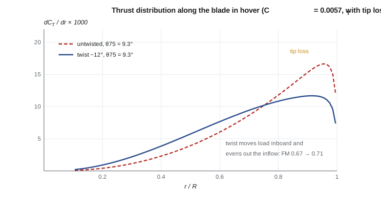
print(f"Tip loss at theta_75 = 9 deg, twist -12 deg: C_T {CT:.5f} without, {CT2:.5f} with ({(1-CT2/CT)*100:.1f} % less thrust)")Solidity 0.0741; required C_T = 0.00573 (C_T/sigma = 0.077) twist 0.0 deg: theta_75 = 9.32 deg, C_P = 0.000457, FM = 0.671, rotor power 493 kW twist -8.0 deg: theta_75 = 9.34 deg, C_P = 0.000436, FM = 0.704, rotor power 470 kW twist -12.0 deg: theta_75 = 9.34 deg, C_P = 0.000430, FM = 0.714, rotor power 463 kW twist -16.0 deg: theta_75 = 9.32 deg, C_P = 0.000427, FM = 0.719, rotor power 460 kW Tip loss at theta_75 = 9 deg, twist -12 deg: C_T 0.00556 without, 0.00546 with (1.8 % less thrust)
For each twist, the code adjusts the collective pitch at 75 per cent radius until the rotor lifts 3000 kg, then reports the power coefficient and figure of merit. All four rotors need about 9.3 degrees at 75 per cent radius, as the three-quarter-radius rule predicts. Twist changes the power: going from an untwisted blade to −12 degrees raises the figure of merit from 0.67 to 0.71 and saves 30 kW, about 6 per cent of hover power. Going further, to −16 degrees, saves only 3 kW more. Tip loss costs about 2 per cent of the thrust at a given pitch, which the rotor recovers with a little more collective and a little more power.
Why twist helps
An untwisted blade has the same pitch everywhere, but the tangential velocity increases linearly with radius, so the lift per unit span rises as \(r^{2}\). Most of the thrust comes from the outer part of the blade, and the inflow there is large, while the inner part does little. Momentum theory says that for minimum induced power the inflow should be uniform across the disk. Uniform inflow requires the thrust per unit area of each annulus to be the same, which requires the section loading to rise only linearly with radius. The pitch that does this is the ideal twist, \(\theta(r) = \theta_{\text{tip}}/r\): high pitch at the root and low pitch at the tip. It cannot be built exactly, because the root pitch would be infinite, but linear twist of −8 to −16 degrees approximates it well over the outer half of the blade, where most thrust is produced.
Twist is not free. In forward flight, a highly twisted blade carries negative lift near the tip on the advancing side, which raises vibration and profile power; high-speed rotors and tiltrotor blades are a compromise between hover and cruise. Modern blades also vary chord, airfoil section and sweep along the span. Thinner, cambered sections with a high maximum lift coefficient go on the outer part of the blade, where the retreating side needs lift, and thin sections with a high drag-divergence Mach number go at the tip, where the advancing side meets compressibility. Swept or anhedral tips reduce noise and the strength of the tip vortex.
| Design choice | Effect in hover | Effect in forward flight |
|---|---|---|
| More negative twist | Higher figure of merit (to about −16 degrees) | Negative tip lift on the advancing side; more vibration |
| Higher solidity | More profile power; delays blade stall | More thrust margin before retreating blade stall |
| Higher tip speed | Less solidity needed for thrust | Advancing tip Mach number and noise rise |
| Tapered or swept tip | Smaller tip losses | Lower compressibility drag and noise |
| More blades, same solidity | Smaller tip loss; smoother loads | Lower vibration; heavier hub |
Worked problem
Thrust coefficient and blade loading
Find \(C_T\) and \(C_T/\sigma\) for the medevac twin at 3000 kg, sea level, with a tip speed of 210 m/s.
Show solution
- \(C_T = T/(\rho A V_T^{2}) = 29\,430/(1.225 \times 95.03 \times 210^{2}) = 0.00573\).
- \(\sigma = 4 \times 0.32/(\pi \times 5.5) = 0.0741\).
- \(C_T/\sigma = 0.077\).
Answer: \(C_T/\sigma\) is the blade loading coefficient; values of 0.07 to 0.09 in hover leave margin for manoeuvres and forward flight before blade stall.
Worked problem
Collective pitch from the simple formula
Estimate the collective pitch at 75 per cent radius for the medevac twin in hover using uniform inflow and \(a = 5.73\) per radian, and compare it with the code.
Show solution
- \(\lambda = \sqrt{C_T/2} = \sqrt{0.00573/2} = 0.0535\).
- \(\theta_{0.75} = 3(2C_T/(\sigma a) + \lambda/2) = 3(2 \times 0.00573/(0.0741 \times 5.73) + 0.0268)\).
- \(= 3(0.0270 + 0.0268) = 0.161\ \mathrm{rad} = 9.25^{\circ}\).
Answer: About 9.3 degrees, the same as the BEMT result; the code's tip loss and root cut-out roughly cancel.
Worked problem
Hover power from the simple formula
Use \(C_P = \kappa C_T^{3/2}/\sqrt{2} + \sigma c_{d0}/8\) with \(\kappa = 1.15\) and \(c_{d0} = 0.0095\) to estimate the main rotor power.
Show solution
- Induced: \(1.15 \times 0.00573^{1.5}/\sqrt{2} = 1.15 \times 0.000307 = 0.000353\).
- Profile: \(0.0741 \times 0.0095/8 = 0.0000880\).
- \(C_P = 0.000441\); \(P = C_P \rho A V_T^{3} = 0.000441 \times 1.225 \times 95.03 \times 210^{3} = 475\ \mathrm{kW}\).
Answer: About 475 kW, close to the BEMT values of 460 to 490 kW; the figure of merit is 0.70.
Common mistakes
MistakeBlade pitch and angle of attack are the same thing.
InsteadAngle of attack is the pitch minus the inflow angle; at the same pitch, more inflow means less angle of attack.
MistakeThe tip of the blade does the most work, so the tip should have the highest pitch.
InsteadFor uniform inflow the tip needs the lowest pitch; ideal twist makes pitch inversely proportional to radius.
MistakeProfile power is small and can be ignored in hover.
InsteadIt is about 20 to 30 per cent of hover power for a helicopter rotor and more for small drone propellers.
MistakePrandtl tip loss only matters for propellers.
InsteadIt matters for every finite-blade rotor; it costs a few per cent of thrust on a helicopter and more on two-blade and heavily loaded rotors.
Summary and key terms
- Blade element theory splits each blade into spanwise strips and applies two-dimensional airfoil data at the local velocity and angle of attack.
- The angle of attack is the pitch minus the inflow angle, and the backward tilt of lift caused by inflow is the source of induced torque.
- For linear twist, thrust depends on the pitch at 75 per cent radius.
- Power splits into induced power, \(\kappa C_T^{3/2}/\sqrt{2}\), and profile power, \(\sigma c_{d0}/8\).
- Blade element momentum theory equates the blade element and momentum thrust of each annulus to find the inflow distribution, and Prandtl's factor corrects for tip loss.
- Ideal twist gives uniform inflow; practical linear twist of about −8 to −16 degrees captures most of the benefit in hover but is limited by forward flight.
- Blade element
- A short spanwise strip of blade treated as a two-dimensional airfoil.
- Inflow ratio
- Velocity through the disk divided by tip speed, \(\lambda\).
- Solidity
- Blade area divided by disk area, \(\sigma = N_b c/(\pi R)\).
- Linear twist
- Pitch that varies linearly from root to tip, usually decreasing outward.
- BEMT
- Blade element momentum theory: blade element forces matched to momentum theory annulus by annulus.
- Tip loss
- Reduction in lift near the blade tip as air spills from the lower to the upper surface.
- Induced power factor
- \(\kappa\): ratio of actual induced power to the momentum-theory ideal.
- Ideal twist
- Pitch inversely proportional to radius, which gives uniform inflow in hover.
Practice problems
Work each problem on paper first, then reveal the answer to check.
A rotor has three blades of chord 0.08 m and radius 0.9 m. What is its solidity?
Show answer
\(3 \times 0.08/(\pi \times 0.9) = 0.085\).
Why is the induced torque proportional to \(\phi\,dL\)?
Show answer
The lift vector tilts back by the inflow angle, so its in-plane component is \(dL\sin\phi \approx \phi\,dL\).
What does the three-quarter-radius rule state?
Show answer
For linear twist and uniform inflow, thrust equals that of an untwisted blade with the pitch found at 75 per cent radius.
Going from −12 to −16 degrees of twist, how much hover power did the code save?
Show answer
About 3 kW, from 463 to 460 kW: diminishing returns.
How does Prandtl's tip-loss factor change with more blades?
Show answer
With more blades, \(f\) grows and \(F\) stays close to 1 further out, so the tip loss region shrinks.
Lesson quiz · 5 questions
Score 60% or more to complete this lesson.
Create a free account to save your progress, take quizzes and earn a certificate.