
AERO-360 · Lesson 9 of 12 · 25 min
Joining: rivets, bolts, bonding and welding
An airliner contains more than a million fasteners, and a small turboprop such as the Tern Block 2 tens of thousands. Joints are where most fatigue cracks start, where corrosion hides, where composites meet metals and where manufacturing time goes. Choosing how to join two parts is therefore a materials decision as much as a structural one. This lesson covers mechanical fastening with rivets and bolts, adhesive bonding, and welding, and follows Arjun as he checks the joints where the Tern's new composite rear fuselage cone meets the aluminium fuselage, and a lap joint in its wing.
Solid rivets
Solid rivets remain the standard fastener for aluminium skins and stringers. A rivet is a short pin with a manufactured head; it is inserted through matching holes and its tail is upset with a rivet gun and bucking bar, or squeezed, so that it swells to fill the hole and forms a second head. The swelling clamps the sheets and puts the rivet in bearing against the hole walls. Aluminium rivets are usually 2117-T4, which can be driven as received, or 2024-T4 and 7050-T73 rivets for higher strength, some of which must be driven soon after solution treatment or kept refrigerated so they stay soft enough to upset. Countersunk flush rivets keep outer skins smooth for aerodynamics.
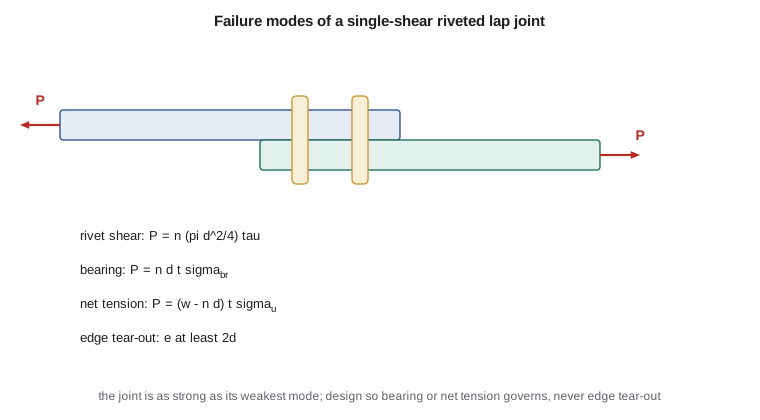
Rivet spacing follows rules developed over decades: edge distance at least about twice the rivet diameter, so the sheet does not tear out; pitch along a row typically four to six diameters; and rows staggered to spread load. Automated drilling and riveting machines now install most rivets on large assemblies, measuring every hole and recording every installation.
Joint strength and failure modes
A mechanically fastened joint can fail in several ways. The fasteners can shear. The sheet can fail in bearing, when the fastener crushes and elongates the hole. The sheet can fail in net tension across the row of holes, where material has been removed. Or the fastener can tear out through the edge if the edge distance is too small. The joint's strength is the lowest of these. Good design makes bearing or net tension govern, because those failures give warning by hole elongation, and never edge tear-out, which is sudden. In fatigue, joints behave differently: the hole is a stress concentration, load transfer through the fastener adds local bending in single-shear joints, and fretting between sheets starts cracks. Fatigue rather than static strength usually sizes fuselage and lower wing joints.
# Single-shear lap joint in the Tern wing: rivet shear, bearing, net tension and edge distance checks.
import math
t, w, n, d = 1.6, 30.0, 2, 4.0          # sheet thickness mm, strip width per rivet column mm, rivets in line, rivet dia mm
tau_r = 260.0                           # shear strength of a 2117-T4-type solid rivet, MPa (illustrative)
br_u, ftu = 880.0, 434.0                # bearing ultimate and tensile ultimate of 2024-T3 sheet, MPa (typical)
e = 2.0 * d                             # edge distance, mm
P_shear = n * math.pi * d ** 2 / 4 * tau_r
P_bear = n * d * t * br_u
P_net = (w - d) * t * ftu               # one rivet row across the strip governs net section
P_tear = n * 2 * (e - d / 2) * t * 0.6 * ftu
modes = {"rivet shear": P_shear, "bearing": P_bear, "net tension": P_net, "edge tear-out": P_tear}
for m, P in sorted(modes.items(), key=lambda x: x[1]):
    print(f"{m:14s} {P/1000:6.2f} kN")
gov = min(modes, key=modes.get)
print(f"governing mode: {gov}; joint strength {modes[gov]/1000:.2f} kN for a {w:.0f} mm strip")
# Bolted titanium fitting on CFRP: bearing on the laminate at a 4.76 mm (3/16 in) bolt
t_c, d_b, br_c = 4.0, 4.76, 650.0       # laminate thickness mm, bolt dia mm, allowable bearing stress MPa (illustrative)
print(f"CFRP bearing capacity per bolt: {t_c * d_b * br_c / 1000:.1f} kN")
# Adhesive lap shear: average shear stress is not the peak; peaks sit at the overlap ends
for L in (12.5, 25.0, 50.0):
    P = 15000.0                        # 15 kN on a 25 mm wide coupon
print(f"overlap {L:4.1f} mm: average shear {P / (L * 25):5.1f} MPa (peak stresses at the ends are higher)")rivet shear 6.53 kN edge tear-out 10.00 kN bearing 11.26 kN net tension 18.05 kN governing mode: rivet shear; joint strength 6.53 kN for a 30 mm strip CFRP bearing capacity per bolt: 12.4 kN overlap 12.5 mm: average shear 48.0 MPa (peak stresses at the ends are higher) overlap 25.0 mm: average shear 24.0 MPa (peak stresses at the ends are higher) overlap 50.0 mm: average shear 12.0 MPa (peak stresses at the ends are higher)
In the program, rivet shear governs at about 6.5 kN, ahead of edge tear-out at 10.0 kN, bearing at 11.3 kN and net tension at 18.1 kN. Arjun points out that the stress engineers prefer bearing to govern, so the joint would gain from rivets one size larger, which raise shear strength by the square of the diameter while bearing grows only linearly. With 4.8 mm rivets the shear strength rises to about 9.4 kN and bearing to about 13.5 kN. Marcus Webb agrees to the change, and the drawing is revised. The adhesive results show the other lesson: doubling the overlap halves the average shear stress, but the peak stresses at the ends of the overlap fall much less, so long overlaps add weight without much strength.
Bolts, blind fasteners and composite joints
Where loads are high or parts must come apart, bolts replace rivets. Aerospace bolts are close-tolerance steel or titanium bolts in holes reamed to a tight interference or clearance fit, with self-locking nuts or collars. Lockbolts and swaged-collar fasteners, such as the common two-piece titanium pin with a swaged aluminium or titanium collar, are installed from both sides and give a consistent clamp load. Blind fasteners, installed from one side, are used where the back of the joint cannot be reached, such as closing out a wing box or a control surface.
Composites change the fastener rules. Aluminium fasteners are not used in carbon fibre because of galvanic corrosion, so titanium or corrosion-resistant steel fasteners are installed wet with sealant. Holes must be drilled carefully to avoid delamination, and fasteners with large heads or washers spread the bearing load, because composites are weaker in bearing than metals and have no ductility to redistribute load between fasteners. Bearing allowables for laminates depend on the layup, edge distance, clamp-up and hot-wet condition. Fasteners in lightning strike zones must also carry current without sparking. The program's bearing capacity of about 12 kN for a 4.76 mm bolt in a 4 mm laminate is typical; the Tern's composite rear cone joint uses titanium lockbolts of that size with liquid shim to fill gaps.
Adhesive bonding
Adhesive bonding spreads load over an area instead of concentrating it at holes, seals the joint, avoids drilling fibres and can save weight. Aircraft have been bonded since the 1940s, from metal-to-metal bonded fuselage doublers to honeycomb panels and composite stiffeners. Structural adhesives are epoxy films or pastes cured at 120 or 180 °C, often with a carrier fabric to control bondline thickness. Bond strength depends almost entirely on the surface. Aluminium is prepared by anodizing, usually phosphoric acid anodizing, which grows a porous oxide that the primer and adhesive key into; composites are prepared by removing a peel ply and sometimes abrading. Contamination produces weak bonds that look perfect.
That problem shapes certification. Because a weak bond cannot be reliably detected by today's nondestructive inspection, regulators require that bonded primary structure either show, by test and analysis, that disbonds up to a set size cannot grow to critical before they are found, or include fasteners that keep limit load if the bond fails, or prove each bond by proof testing. Many composite stiffeners on large aircraft are therefore co-cured with their skins, and bonded repairs are limited in size unless backed by fasteners.
Welding
Welding is less common in airframes than in other industries because the heat lowers the strength of heat-treated aluminium, and the 2xxx and 7xxx alloys are hard to fusion weld without cracking. It is widely used elsewhere. Gas tungsten arc welding joins titanium, stainless steel and nickel alloys in engine parts, exhaust systems and ducts, always with full inert gas shielding. Electron beam welding in vacuum makes deep, narrow welds in engine rotor parts. Resistance spot welding joins some stainless and titanium sheet parts. Linear friction welding attaches blades to discs to make one-piece bladed discs, or blisks. Friction stir welding, in which a rotating tool stirs metal together below its melting point, joins aluminium alloys that cannot be fusion welded, and is used in launch vehicle fuel tanks and some business jet fuselages and floors.
| Method | Typical use | Strengths | Watch for |
|---|---|---|---|
| Solid rivets | aluminium skins and stringers | cheap, reliable, inspectable | fatigue at holes, corrosion in joints |
| Bolts and lockbolts | fittings, composite joints | high load, consistent clamp | hole quality, galvanic pairs |
| Blind fasteners | closed boxes, repairs | one-sided access | lower strength, inspection |
| Adhesive bonding | stiffeners, doublers, sandwich panels | no holes, sealed, light | surface prep, weak bond detection |
| Fusion welding | titanium, steel, nickel parts | one-piece structure | heat-affected zone, distortion |
| Friction stir welding | aluminium tanks, panels | joins hard-to-weld alloys | tool marks, root defects |
Installation quality and inspection of joints
Most joint problems found in service begin as installation defects. A rivet driven at an angle, a hole drilled oversize or with burrs, a missing sealant bead, or a fastener installed with the wrong grip length can each start fatigue cracks or corrosion years later. Manufacturers control installation through process specifications that set hole tolerances, countersink depths, rivet head heights and diameters, torque or swage values, and sealant coverage. Inspectors check upset rivet heads with gauges, sample holes for diameter and finish, and witness sealant application. Automated drilling machines record every hole's diameter and position, and fastening machines record installation force, so a defect can be traced to its machine, operator and date.
Composite joints need extra care at the drill. Carbon fibre wears tools quickly, and a dull drill pushes out the last plies as it exits, causing exit delamination. Shops use carbide or diamond-coated drills, backing plates, controlled feed and frequent tool changes, and inspect a sample of holes by ultrasound. Gaps between composite and metal parts larger than a set limit, often about 0.13 mm, are filled with liquid shim before fastening, because clamping a gap bends the laminate and can crack it. When the Tern's rear cone was first fitted to the fuselage, Arjun measured gaps of up to 0.6 mm at two frames; the shop filled them with liquid shim, let it cure, and drilled through it to final size.
In service, joints are among the most inspected areas of an aircraft. Lap joints in pressurized fuselages, where widespread fatigue damage can link small cracks at many neighbouring fasteners, are covered by special inspection programs and limits of validity that cap the number of flights an airframe may make unless the joints are modified. Fasteners in high-load fittings are removed at intervals so the holes can be inspected with eddy current probes, then reinstalled at the next oversize.
Worked problem
Rivet shear
Two 4.0 mm rivets with a shear strength of 260 MPa carry a single-shear joint. Find the shear capacity.
Show solution
- Area of one rivet \(= \pi \times 4.0^2/4 = 12.57\) mm².
- \(P = 2 \times 12.57 \times 260 = 6535\) N.
Answer: About 6.5 kN.
Worked problem
Bearing
Find the bearing capacity of the same joint in 1.6 mm sheet with a bearing ultimate of 880 MPa.
Show solution
- \(P = n d t \sigma_{br} = 2 \times 4.0 \times 1.6 \times 880 = 11\,264\) N.
Answer: About 11.3 kN, so rivet shear governs.
Worked problem
Edge distance
A 4.8 mm rivet is placed 7.0 mm from the sheet edge. Does it meet a 2d edge distance rule?
Show solution
- Required \(2d = 9.6\) mm.
- 7.0 mm is less than 9.6 mm.
Answer: No; the rivet must move inward or the sheet must be wider.
Common mistakes
MistakeDesigning so edge tear-out governs.
InsteadEdge tear-out is sudden; make bearing or net tension govern.
MistakeUsing aluminium fasteners in carbon fibre.
InsteadAluminium corrodes against carbon; use titanium or corrosion-resistant steel installed wet.
MistakeAssuming a long adhesive overlap is proportionally stronger.
InsteadPeak stresses at the ends limit strength; long overlaps add little.
MistakeFusion welding 7075 like steel.
InsteadHigh-strength aluminium alloys crack and lose strength; friction stir welding or mechanical joints are used.
Summary and key terms
- Aircraft structure is joined mainly with solid rivets, bolts and lockbolts, blind fasteners, adhesive bonding and, in some places, welding.
- A mechanical joint fails by fastener shear, bearing, net tension or edge tear-out; designers aim for bearing or net tension to govern and keep edge distance at least twice the diameter.
- Composite joints use titanium fasteners installed wet and are weaker in bearing.
- Bonded joints depend on surface preparation and need fail-safe features for certification because weak bonds are hard to detect.
- Welding is used for titanium, steel and nickel parts, and friction stir welding joins aluminium alloys that fusion welding cannot.
- Bearing failure
- Crushing and elongation of a hole by the fastener pressing on its wall.
- Net tension
- Tensile failure across the reduced section through a row of holes.
- Edge distance
- The distance from a fastener centre to the edge of the part.
- Lockbolt
- A pin and swaged collar fastener installed with consistent clamp load.
- Kissing bond
- A bonded joint in contact but with almost no strength, very hard to detect.
- Friction stir welding
- Solid-state joining by a rotating tool that stirs metal together below its melting point.
Practice problems
Work each problem on paper first, then reveal the answer to check.
In the program, which failure mode governs the two-rivet joint?
Show answer
Rivet shear, at about 6.5 kN.
Why does a larger rivet make bearing govern?
Show answer
Shear strength rises with diameter squared, bearing only with diameter.
Why are blind fasteners used?
Show answer
They can be installed with access from only one side.
How is aluminium usually prepared for structural bonding?
Show answer
Phosphoric acid anodizing followed by primer.
Why do many certified bonded joints include fasteners?
Show answer
So the joint keeps limit load if an undetected weak bond fails.
What process joins blades to discs to make blisks?
Show answer
Linear friction welding.
Lesson quiz · 5 questions
Score 60% or more to complete this lesson.
Create a free account to save your progress, take quizzes and earn a certificate.