
AERO-360 · Lesson 10 of 12 · 25 min
Additive manufacturing
Additive manufacturing builds a part layer by layer from powder, wire or resin instead of cutting it from a larger block. In aerospace it has moved in a decade from prototypes to flying parts: fuel nozzle tips in airliner engines, brackets, ducts, housings, heat exchangers and some rocket engine parts are now printed. Its attractions are freedom of shape, near-net builds that cut titanium buy-to-fly ratios, part consolidation and short lead times. Its challenge is qualification, because a printed part's properties depend on every detail of the process. This lesson follows the Swift 900 study's titanium pylon bracket from Lesson 3 as Odile Marchetti's group plans to print it for the prototype aircraft.
Processes
Laser powder bed fusion, LPBF, is the most widely used metal process for small, detailed parts. A thin layer of powder, about 20 to 60 µm, is spread across a build plate in an inert atmosphere, and one or more lasers melt the cross-section of the part. The plate drops, a new layer is spread, and the cycle repeats thousands of times. Electron beam powder bed fusion works similarly in vacuum with an electron beam and a heated powder bed, which reduces residual stress in titanium and intermetallic parts. Directed energy deposition feeds wire or powder into a melt pool made by a laser, electron beam or arc, and builds large, coarser parts quickly; wire arc additive manufacturing can make metre-scale titanium preforms that are then machined.
Polymer processes matter too. Powder bed fusion of nylon and PEKK makes environmental control system ducts and interior brackets; fused filament fabrication with high-temperature thermoplastics such as ULTEM makes cabin parts, tooling and jigs; and continuous fibre printing is emerging for lightly loaded composite parts. Much of the industry's early value from additive manufacturing has come from tooling: drill templates, layup aids and inspection fixtures printed in days instead of machined in weeks.
Design for additive manufacturing
Printing an existing part designed for machining wastes most of the benefit. Design for additive manufacturing uses the process's freedom: topology optimization places material only where load paths need it, producing organic, lattice or hollow shapes; several parts become one, eliminating fasteners and joints; internal cooling or fuel channels follow curved paths no drill could reach. The famous example is a fuel nozzle tip that replaced an assembly of about twenty brazed parts with a single printed part, lighter and more durable.
Design must also respect the process. Overhangs flatter than about 45 degrees from the build plate need support structures that are later removed. Thin walls distort, and large flat areas curl from residual stress. Surfaces facing down are rougher than those facing up. Holes and mating faces are usually printed slightly undersize and finish machined. Build orientation is chosen to balance supports, distortion, surface finish and the direction of the strongest properties, because printed metals can be anisotropic: properties along the build direction often differ from those across it.
Microstructure, defects and post-processing
Each layer melts and solidifies in milliseconds, so printed metals have very fine, often columnar microstructures and high residual stresses. Titanium printed by LPBF forms fine martensite that is strong but less ductile. Defects come mainly as porosity: gas pores from trapped gas, and lack-of-fusion voids where layers did not fully melt together, which are larger, irregular and far more harmful to fatigue. Surface roughness and near-surface pores also lower fatigue strength well below that of wrought metal unless the surface is machined.
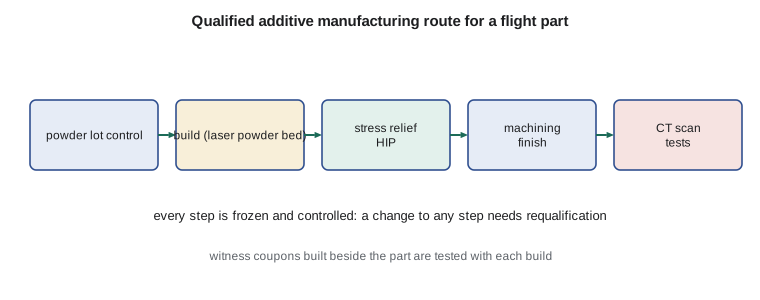
Post-processing therefore does much of the work. Parts are stress relieved while still on the build plate, cut off, and usually hot isostatically pressed: heated to near the annealing temperature under high-pressure argon, which closes internal pores that are not open to the surface and coarsens the microstructure for better ductility and fatigue. Supports are removed, critical surfaces are machined, and the part is heat treated to its specified condition. After HIP and machining, printed Ti-6Al-4V can match or approach wrought properties in static strength and come close in fatigue.
# Laser powder bed fusion of a Ti-6Al-4V bracket: build time, density from porosity and witness coupon results.
import math
part_vol = 410.0                        # cm3 of solid in the part (after design for additive)
supports = 0.18                         # support volume as a fraction of part volume
layer, hatch, v_scan = 0.03, 0.12, 1200.0   # mm, mm, mm/s
lasers = 4
build_rate = layer * hatch * v_scan * 3600 / 1000 * lasers   # cm3/h
height_mm, recoat_s = 140.0, 9.0
layers = height_mm / layer
t_melt = part_vol * (1 + supports) / build_rate
t_recoat = layers * recoat_s / 3600
print(f"melt rate {build_rate:.0f} cm3/h with {lasers} lasers; melting {t_melt:.1f} h, recoating {t_recoat:.1f} h, "
      f"total about {t_melt + t_recoat:.0f} h")
rho_full = 4.43
for pores in (0.5, 0.1, 0.02):
    print(f"porosity {pores:.2f}% -> density {rho_full * (1 - pores / 100):.3f} g/cm3")
# Witness coupon tensile results for one build (MPa); acceptance: every coupon at or above the minimum
uts = [1012, 1018, 998, 1025, 1009, 1003]
mean = sum(uts) / len(uts); sd = (sum((x - mean) ** 2 for x in uts) / (len(uts) - 1)) ** 0.5
print(f"\nwitness UTS mean {mean:.0f} MPa, s.d. {sd:.1f} MPa, minimum {min(uts)} MPa")
print("build accepted" if min(uts) >= 930 else "build rejected")melt rate 62 cm3/h with 4 lasers; melting 7.8 h, recoating 11.7 h, total about 19 h porosity 0.50% -> density 4.408 g/cm3 porosity 0.10% -> density 4.426 g/cm3 porosity 0.02% -> density 4.429 g/cm3 witness UTS mean 1011 MPa, s.d. 9.8 MPa, minimum 998 MPa build accepted
The program estimates a melt rate of about 62 cm³/h with four lasers and a build of about 19 hours, of which more than half is spent spreading new powder layers. That is one reason operators fill each build plate with as many parts as fit: recoating time is shared. Density changes very little with porosity, from 4.429 to 4.408 g/cm³ between 0.02 and 0.5 percent, which shows why density measurement alone cannot qualify a part; computed tomography and fatigue tests are needed to find the size and location of pores. The witness coupons all exceed the 930 MPa minimum assumed for the material specification, so the build is accepted.
Qualification and certification
A printed flight part's properties are set by its feedstock, machine, laser parameters, scan strategy, build orientation, location on the plate and post-processing. Qualification therefore freezes the whole process. The powder specification controls chemistry, particle size distribution, flowability and the number of times powder may be reused. Each machine is qualified, its parameters locked and its sensors monitored. Builds include witness coupons for tensile, fatigue and chemistry tests. Parts are inspected, often by computed tomography for complex internal features. Any change, a new machine, a parameter update, a powder supplier, needs requalification, scaled to the part's criticality.
Regulators approve printed parts within existing rules for materials and processes, which require that material properties be established statistically and processes be controlled. Transport Canada and other authorities have worked with industry on guidance and standards, and industry groups such as SAE have published AMS specifications for printed titanium and nickel alloys and their powders. Parts are typically classified by criticality: non-structural interior parts are straightforward; secondary structure needs more data; and fracture-critical primary structure, whose failure would endanger the aircraft, requires the most extensive testing and is still rare. the composite manufacturing plants and engine repair shops around Winnipeg have both been active in additive research, testing and supplier qualification.
| Process | Feedstock | Typical parts | Notes |
|---|---|---|---|
| Laser powder bed fusion | metal powder | brackets, fuel nozzles, heat exchangers | fine detail, small to medium parts |
| Electron beam powder bed | metal powder | titanium and intermetallic parts | hot bed lowers residual stress |
| Directed energy deposition | powder or wire | large preforms, repairs | fast, coarse, needs machining |
| Wire arc additive | wire | large titanium preforms | very low buy-to-fly before machining |
| Polymer powder bed | nylon, PEKK powder | ducts, interior brackets | low cost per part |
| Fused filament fabrication | thermoplastic filament | tooling, jigs, cabin parts | quick and cheap |
Repair and spare parts
Additive processes also repair parts. Directed energy deposition rebuilds worn compressor blade tips, seal lands and flanges on engine casings, restoring parts that would otherwise be scrapped, and cold spray deposits metal powder at high speed without melting to restore corroded or worn surfaces on aluminium and magnesium parts. For out-of-production aircraft, printing replacement parts from digital files avoids remaking obsolete tooling, provided the printed part is approved for the aircraft. Spare parts on demand, printed near the operator, are a long-term goal for airlines and militaries alike.
Process monitoring and the digital thread
Because properties depend on every layer, powder bed machines are fitted with sensors that watch each build. Cameras photograph each spread layer to catch streaks or short feeds of powder; photodiodes and cameras watch the melt pool for changes in brightness or size that may signal lack of fusion or overheating; oxygen sensors confirm the argon atmosphere stays below its limit. The data are stored layer by layer with the part's serial number. Today these records support investigations and the gradual reduction of post-build inspection; the long-term aim is to accept parts partly from monitoring data, but regulators and manufacturers still rely mainly on coupons, inspection and frozen processes.
The records are part of a wider digital thread that links the design model, build file, machine logs, powder lot, heat treatment chart, inspection results and test data for each part. If a coupon fails or a part cracks in service, engineers can trace every other part built from the same powder lot, on the same machine or with the same parameter set. Powder itself is tracked closely: unused powder is sieved and reused, but each reuse changes its oxygen content and particle shape, so specifications limit reuse cycles or oxygen pickup and require testing of blended lots.
Economics and where additive fits
Additive manufacturing is not always cheaper. Powder bed machines are expensive and slow compared with machining aluminium, and post-processing, inspection and qualification add large costs. Additive parts pay off where they replace expensive titanium or nickel removed by machining, where they consolidate many parts into one, where complex internal passages cannot be made otherwise, or where volumes are low and tooling would be costly. Lesson 3's comparison showed this: for the pylon bracket, additive manufacture cost more per part than forging at the assumed volume, but Odile notes that for the prototype aircraft, with only a handful of parts and design changes still likely, it avoids forging dies that would cost more than the whole prototype batch. For production, the choice will be revisited once the design is frozen and volumes are known.
Worked problem
Melt rate
One laser scans at 1200 mm/s with a 0.12 mm hatch spacing and a 0.03 mm layer. Find its melt rate in cm³/h.
Show solution
- Volume rate \(= 0.03 \times 0.12 \times 1200 = 4.32\) mm³/s.
- \(4.32 \times 3600/1000 = 15.6\) cm³/h.
Answer: About 15.6 cm³/h per laser, or about 62 cm³/h with four.
Worked problem
Layer count
A part is 140 mm tall and built in 0.03 mm layers with 9 s of recoating per layer. Find the recoating time.
Show solution
- Layers \(= 140/0.03 = 4667\).
- Time \(= 4667 \times 9/3600 = 11.7\) h.
Answer: About 11.7 hours, regardless of how many parts share the plate.
Worked problem
Buy-to-fly comparison
The printed bracket uses 2.9 kg of powder, including supports and machining stock, for a 1.8 kg part. Compare its buy-to-fly ratio with a 12 to 1 plate route.
Show solution
- Additive: \(2.9/1.8 = 1.6\).
- Plate: 12.
Answer: The additive route buys about one-seventh as much titanium.
Common mistakes
MistakePrinting a part designed for machining.
InsteadRedesign for additive manufacturing to consolidate parts and remove unneeded material.
MistakeQualifying a part by its density.
InsteadSmall porosity changes density little; computed tomography and fatigue tests find harmful defects.
MistakeAssuming printed properties are the same in every direction.
InsteadPrinted metals can be anisotropic; build orientation is part of the specification.
MistakeChanging powder supplier or machine settings freely.
InsteadThe whole process is frozen; changes need requalification.
Summary and key terms
- Additive manufacturing builds parts layer by layer by powder bed fusion, directed energy deposition and polymer processes.
- It offers design freedom, part consolidation, low buy-to-fly ratios and short lead times.
- Printed metals have fine microstructures, residual stresses and porosity, especially lack-of-fusion voids that harm fatigue; stress relief, hot isostatic pressing, machining and heat treatment bring properties close to wrought.
- Qualification freezes powder, machine, parameters and post-processing, uses witness coupons and computed tomography, and scales with part criticality.
- Laser powder bed fusion
- A process that melts thin layers of metal powder with a laser to build a part.
- Directed energy deposition
- A process that melts wire or powder fed into a melt pool to build or repair parts.
- Lack-of-fusion void
- An irregular defect where layers did not fully melt together.
- Hot isostatic pressing
- Heating under high-pressure gas to close internal porosity.
- Witness coupon
- A test specimen built beside a part to verify the build.
- Topology optimization
- A design method that places material only along the required load paths.
Practice problems
Work each problem on paper first, then reveal the answer to check.
In the program, how long does the bracket build take, and what takes most of it?
Show answer
About 19 h, with recoating taking about 11.7 h.
Why are lack-of-fusion voids worse than gas pores?
Show answer
They are larger and irregular, so they start fatigue cracks more easily.
What does hot isostatic pressing do?
Show answer
It closes internal pores and improves ductility and fatigue.
Why are overhangs limited to about 45 degrees?
Show answer
Flatter overhangs need supports to avoid collapse and distortion.
Name one way additive processes repair parts.
Show answer
Rebuilding blade tips or seal lands by directed energy deposition, or restoring surfaces by cold spray.
Why is computed tomography used on printed parts?
Show answer
It finds internal pores and checks internal features.
Lesson quiz · 5 questions
Score 60% or more to complete this lesson.
Create a free account to save your progress, take quizzes and earn a certificate.