
WLD-330 · Lesson 9 of 12 · 17 min
Volumetric NDE: radiography and ultrasonics
Visual, penetrant and magnetic particle testing see the surface. To see inside a weld, inspectors use radiography, which records radiation passing through the weld on film or a digital detector, and ultrasonic testing, which sends high-frequency sound into the weld and listens for echoes. On the Riverside bridge every complete-penetration flange splice is ultrasonically tested; on the Unit 4 spools a random share of the butt welds is radiographed. Devon has seen both done and has had his own welds rejected by both. In this lesson he learns how each works, what each finds and misses, and how the results are judged, so that he can read a report and understand why a weld was cut out.
Radiography: the principle
In radiographic testing, a source of X-rays or gamma rays is placed on one side of the weld and a film or digital detector on the other. Radiation passes through the metal and is absorbed more where the metal is thicker or denser and less where there is a void. A pore, a slag inclusion or incomplete penetration lets more radiation through and shows as a darker area on film; dense inclusions such as tungsten show lighter. The result is a shadow picture of the weld that can be kept as a permanent record and reviewed later by another interpreter, which is one of the method's great strengths.
Gamma radiography with an iridium-192 or selenium-75 source is common in the field and for pipe because the source needs no power and can be put inside the pipe; X-ray tubes give better image quality and are common in shops. Digital radiography with imaging plates or flat-panel detectors has replaced film in many places, with faster results and less chemistry, and codes now accept it under their rules for image quality.
Radiography uses ionizing radiation and is tightly regulated. In the United States, industrial radiography is licensed by the Nuclear Regulatory Commission or, in Agreement States such as Texas, by the state radiation control program, and radiographers must be trained and certified; outside a permanent facility a radiographer must be accompanied by at least one other qualified person. Hartwell does not hold sources; it hires a licensed radiography company, which sets up a restricted area with barriers, signs and survey meters, and Hartwell's crews stay out of it until the radiographers declare it clear. Devon's job during a radiography shift is to have the welds ready, marked and accessible, and then to keep away.
Image quality
A radiograph is useful only if it is sharp and sensitive enough to show the discontinuities the criteria care about. Sensitivity is proved on every image with an image quality indicator, or IQI: a small plaque with holes of set diameters, or a set of wires of graded diameters, placed on the source side of the weld. The code tables say which IQI and which hole or wire must be visible for each material thickness; if it cannot be seen, the image is not acceptable, whatever the weld looks like. Density, or for digital images the signal-to-noise ratio and contrast, must also be within the stated range.
Sharpness depends on geometry. A radiation source is not a point; it has a size, and the shadow of an edge in the weld is blurred by an amount called geometric unsharpness. It grows with the size of the source and with the distance from the object to the detector, and shrinks as the source is moved further away. Codes limit it according to thickness, so the radiographer chooses a source-to-object distance long enough to keep the unsharpness within the limit.
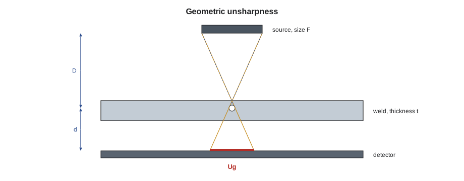
# Geometric unsharpness and the minimum source-to-object distance (limits of the kind ASME Section V gives)
U = 'in'
LIMITS = [(2, 0.020), (3, 0.030), (4, 0.040), (1e9, 0.070)]          # (thickness up to, maximum Ug)
def ug_limit(t):
    return next(u for upto, u in LIMITS if t <= upto)

F = 0.12                 # effective source size
for t, d in [(0.432, 0.6), (1.125, 1.25), (2.375, 2.6)]:    # material thickness, object-to-detector distance
    lim = ug_limit(t)
    D_min = F * d / lim
    print(f"t = {t} {U}: Ug limit {lim} {U}, object-to-detector {d} {U}, minimum source-to-object distance {D_min:.0f} {U}")

D_used = 12
t, d = (1.125, 1.25)
ug = F * d / D_used
print(f"check: D = {D_used} {U} gives Ug = {ug:.3f} {U} -> {'within' if ug <= ug_limit(t) else 'over'} the limit")t = 0.432 in: Ug limit 0.02 in, object-to-detector 0.6 in, minimum source-to-object distance 4 in t = 1.125 in: Ug limit 0.02 in, object-to-detector 1.25 in, minimum source-to-object distance 8 in t = 2.375 in: Ug limit 0.03 in, object-to-detector 2.6 in, minimum source-to-object distance 10 in check: D = 12 in gives Ug = 0.012 in -> within the limit
For the flange neck, the minimum source-to-object distance works out to about 7.5 in; the 12 in the radiographer plans gives an unsharpness well inside the limit. On the thicker vessel shell the minimum distance grows, because the detector sits further from the near side of the weld. The limits in the program follow the pattern in ASME Section V; the radiographer's written technique sheet records the actual distances and source size used for each shot.
What radiography finds and misses
Radiography is best at finding volumetric discontinuities: porosity, slag, incomplete penetration with a gap, and burn-through. It finds cracks and lack of fusion only when they lie roughly parallel to the beam; a planar discontinuity lying across the beam has almost no thickness in the beam direction and may not show. It gives a good picture of the length and position of a discontinuity along the weld but little information about its depth. It needs access to both sides, and it is slow on thick sections. These limits are why bridge codes require ultrasonic testing for complete-penetration welds in tension, where planar discontinuities matter most.
Interpreting a radiograph takes training. The interpreter checks first that the image is valid, with the right IQI visible, the right density and the identification and location markers present. Then the weld is examined for indications, each is classified as porosity, slag, incomplete penetration, lack of fusion, crack, tungsten, undercut, burn-through or other, and measured against the acceptance criteria. Codes often give charts of acceptable rounded indications for each thickness, so that the interpreter can compare the pattern on the film with the chart.
Ultrasonic testing: the principle
Ultrasonic testing sends short pulses of sound, typically a few megahertz, into the metal from a transducer held against the surface with a couplant such as gel or water. Sound travels through sound metal and reflects from any interface: the back wall, a crack, lack of fusion or an inclusion. The instrument displays the echoes against time, which it converts to distance. For welds the usual technique is angle-beam testing, in which a wedge sends the sound into the plate at an angle, often 45, 60 or 70 degrees, so that it crosses the weld from the side, reflecting off the back wall to reach the upper part of the weld on its second leg.
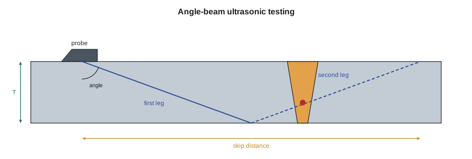
The geometry is simple trigonometry. If the beam enters at angle θ measured from the normal to the surface, a reflector at sound path S on the first leg lies at depth S cos θ and at surface distance S sin θ from the probe's exit point. The beam reaches the back wall after a sound path of T / cos θ and returns to the top surface one skip distance, 2T tan θ, from the probe. On the second leg the depth is measured upward from the back wall. Modern instruments do this calculation and show depth and distance directly, but an inspector must understand it to check that the whole weld is covered.
# Angle-beam UT: locate a reflector from its sound path, and check coverage of the weld
import math
U = 'in'
T = 1.0                 # plate thickness
theta = 70           # beam angle from the normal, degrees
a = math.radians(theta)
leg = T / math.cos(a)
skip = 2 * T * math.tan(a)
print(f"{theta} deg probe on {T} {U} plate: first leg sound path {leg:.1f} {U}, skip distance {skip:.1f} {U}")
for S in [1.9, 3.75, 4.75]:       # sound paths read from the screen
    surface = S * math.sin(a)
    if S <= leg:
        depth = S * math.cos(a)
        where = 'first leg'
    else:
        depth = 2 * T - S * math.cos(a)
        where = 'second leg'
    print(f"sound path {S} {U}: surface distance {surface:.1f} {U}, depth {depth:.1f} {U} ({where})")
# the probe must scan from about half a skip to a full skip from the weld center to cover it with both legs
print(f"scan from about {skip / 2:.0f} to {skip:.0f} {U} from the weld axis")70 deg probe on 1.0 in plate: first leg sound path 2.9 in, skip distance 5.5 in sound path 1.9 in: surface distance 1.8 in, depth 0.6 in (first leg) sound path 3.75 in: surface distance 3.5 in, depth 0.7 in (second leg) sound path 4.75 in: surface distance 4.5 in, depth 0.4 in (second leg) scan from about 3 to 5 in from the weld axis
On the 1 in flange plate with a 70 degree probe, the first leg is long and the skip distance is wide, so the probe must move back and forth over a band well away from the weld. The reflector at the shortest sound path lies on the first leg, low in the weld; the other two lie on the second leg, higher up. Lucia uses this calculation to check that the technician's scan pattern on the report covers the full weld volume.
Evaluating ultrasonic indications
Ultrasonic acceptance in the structural codes is based on how strong an echo is compared with a reference reflector, and how long the indication is. The instrument is calibrated on a standard block with a known reflector, setting a reference level. Each indication is maximized and its level recorded; the code then subtracts the reference level and an allowance for sound attenuation along the path to give an indication rating. Tables give, for each thickness and probe angle, which ratings are rejectable at any length, which are limited in length and which are ignored. Pressure and piping codes more often use criteria based on the measured size of the indication.
Structural-code evaluation subtracts an attenuation factor of about 2 dB per inch of sound path beyond the first inch. Annika's report on the Riverside flange splice FS-07 lists an indication with an echo 6 dB above the reference level at a long sound path; after the attenuation allowance its rating puts it in the class that is limited by length, and its length on the report is within the limit, so it is accepted and recorded. A second indication on FS-11 is rejectable at any length, and the splice goes back to Hartwell for repair.
Newer techniques give much more information. Phased array ultrasonic testing, PAUT, uses a probe with many small elements fired in sequence to sweep the beam through a range of angles and build an image of the weld cross-section, with the data recorded for review like a radiograph. Time-of-flight diffraction, TOFD, uses two probes on either side of the weld and times the diffracted signals from the tips of a discontinuity, giving an accurate measure of its height. Both are accepted under recent code editions with qualified procedures and qualified technicians, and both are increasingly used in place of radiography on pipe and vessels because they avoid radiation hazards and find planar discontinuities well.
Choosing and planning volumetric testing
| Point | Radiography | Ultrasonics |
|---|---|---|
| Best at finding | Porosity, slag, gaps | Cracks, lack of fusion and other planar discontinuities |
| Access | Both sides | One side |
| Record | Permanent image | Report, or recorded data with PAUT and TOFD |
| Depth information | Little | Good |
| Safety | Radiation; area must be cleared | No radiation hazard |
| Thickness | Slower on thick sections | Works well on thick sections; thin sections need special care |
The amount of volumetric testing is set by the code and the contract: all welds of a type, a percentage chosen at random, or a percentage chosen by the inspector. Random selection must be genuinely random and must spread across welders and joint types, or it proves nothing. When a random examination finds a rejectable weld, codes such as B31.3 require more welds by the same welder to be examined, the progressive examination Devon met in the pipe course.
# A random selection for partial examination that represents every welder (fixed seed so the plan can be audited)
import random
random.seed(20261102)
welds = [f'W{n:03d}' for n in range(1, 47)]
welder = {w: ('D. Okafor' if i % 3 == 0 else 'M. Kowalchuk' if i % 3 == 1 else 'R. Haldane') for i, w in enumerate(welds)}
percent = 5
need = max(1, -(-len(welds) * percent // 100))   # round up
chosen = []
for name in sorted(set(welder.values())):         # at least one weld from each welder
    chosen.append(random.choice([w for w in welds if welder[w] == name]))
rest = [w for w in welds if w not in chosen]
while len(chosen) < need:
    chosen.append(rest.pop(random.randrange(len(rest))))
print(f"{len(welds)} butt welds, {percent} percent means at least {need}; selected {len(chosen)}:")
for w in sorted(chosen):
print(f" {w} {welder[w]}")46 butt welds, 5 percent means at least 3; selected 3: W007 D. Okafor W020 M. Kowalchuk W033 R. Haldane
Five percent of 46 welds rounds up to three, and because each of the three welders must be represented, the selection takes one weld from each. The fixed seed means the selection can be reproduced at an audit. On Unit 4 the refinery's inspector makes the selection, not Hartwell, but the principle of covering every welder is the same.
Common mistakes
MistakeReading a radiograph without checking the IQI.
InsteadIf the required IQI hole or wire is not visible, the image is not valid.
MistakeAssuming radiography finds every crack.
InsteadPlanar discontinuities across the beam may not show; ultrasonics finds them better.
MistakeIgnoring the second leg in angle-beam testing.
InsteadScan far enough back that both legs cover the whole weld.
MistakeChoosing random welds from one welder's work.
InsteadRandom selection must represent every welder and joint type.
MistakeWalking into a radiography area to fetch a tool.
InsteadStay out until the radiographers declare the area clear.
Summary and key terms
- Radiography records radiation through the weld; ultrasonics records echoes of sound.
- Image quality indicators prove radiographic sensitivity; geometric unsharpness limits set source distance.
- Radiography finds volumetric discontinuities best; ultrasonics finds planar ones best.
- Angle-beam geometry gives depth, surface distance and skip distance from the sound path and angle.
- Ultrasonic indications are rated against a reference reflector and judged by rating and length.
- Partial examination must be random and represent every welder.
- Radiographic testing
- Examination by radiation passing through the weld onto a film or detector.
- Image quality indicator
- A plaque or wire set whose visible features prove radiographic sensitivity.
- Geometric unsharpness
- Blurring of edges on a radiograph caused by source size and geometry.
- Ultrasonic testing
- Examination by pulses of high-frequency sound and their echoes.
- Skip distance
- The surface distance in which an angle beam travels down to the back wall and back up.
- Phased array
- An ultrasonic technique that sweeps a beam electronically and builds an image.
Practice problems
Work each problem on paper first, then reveal the answer to check.
A 70 degree probe on 1 in plate: what is the skip distance?
Show answer
2 × 1 × tan 70° ≈ 5.5 in.
Which method is better for finding lack of sidewall fusion?
Show answer
Ultrasonic testing.
Five percent of 46 welds by three welders: how many must be selected?
Show answer
At least three, one from each welder.
Lesson quiz · 5 questions
Score 60% or more to complete this lesson.
Create a free account to save your progress, take quizzes and earn a certificate.