
WLD-220 · Lesson 5 of 12 · 17 min
The welding symbol: reference line, arrow and tail
A drawing of a welded assembly can have hundreds of welds on it. Drawing each one in section would take forever and fill the sheet. Instead, drafters use the welding symbol: a small, standard sign attached to the joint by an arrow, which says what kind of weld to make, on which side, how big, how long, how it is to be finished, and which procedure or specification applies. A welder who reads welding symbols fluently can look at a busy assembly drawing and know every weld on it. This lesson covers the frame of the welding symbol, the reference line, the arrow and the tail, and the rules that decide which side of the joint a weld goes on. The next lessons fill in the weld symbols that sit on the reference line.
Welding symbol and weld symbol
Two terms that sound alike mean different things.
- The weld symbol is the small graphic character that shows the type of weld: a triangle for a fillet, a V for a V-groove, a single slanted line for a bevel, and so on.
- The welding symbol is the whole assembly: the reference line, the arrow, the tail if there is one, the weld symbol or symbols, the dimensions, the supplementary symbols and any notes.
In North America the system is set out in AWS A2.4, Standard Symbols for Welding, Brazing, and Nondestructive Examination. The current edition is A2.4:2020, and AWS D1.1 requires welding symbols to follow it unless the contract says otherwise. Drawings from Europe and much of the rest of the world use ISO 2553, which looks similar but has important differences, covered at the end of this lesson.
The parts of a welding symbol
Every welding symbol has at least a reference line and an arrow. The other elements are added as needed, and each has a fixed place relative to the reference line, so that a welder always knows where to look.
- Reference line: the horizontal line that everything else is attached to. It is always drawn horizontal on the sheet, even when the arrow points in any direction.
- Arrow: connects the reference line to the joint, and points at the arrow side of the joint.
- Tail: a V-shaped fork at the far end of the reference line, used only when there is something to put in it, such as a process, a procedure number, a specification or a reference to a detail.
- Weld symbol: sits on the reference line, below it for the arrow side and above it for the other side.
- Dimensions: the size goes to the left of the weld symbol; the length and pitch go to its right. Groove angle, root opening and other groove dimensions have their own places, covered in the groove weld lesson.
- Supplementary symbols: the weld-all-around circle and the field weld flag at the junction of the arrow and reference line; contour and finish symbols above or below the weld symbol.
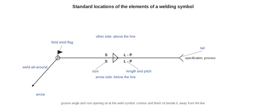
The order of elements reads the same way whichever end the arrow is on. A reference line can have its arrow on the left or on the right, and the tail at the other end. The elements do not mirror: size is still to the left of the weld symbol and length to its right, reading the drawing normally.
Arrow side and other side
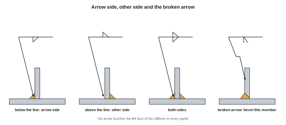
This is the most important rule in the whole system, and the one most often misread. A joint has two sides. The side the arrow touches is the arrow side. The opposite side is the other side.
- A weld symbol placed below the reference line means the weld is on the arrow side.
- A weld symbol placed above the reference line means the weld is on the other side.
- Weld symbols on both sides of the line mean welds on both sides of the joint.
The rule does not depend on which way the arrow points, whether the symbol is above or below the joint on the drawing, or which member is on top in the view. It depends only on where the arrow touches and which side of the reference line the symbol is on. A welder reading a symbol should first find exactly where the arrow touches the joint, then decide which physical side of the joint that is, then look at whether the weld symbol is below or above the line.
On the Coldwater base frame, the gusset at each corner has fillet welds on both sides to the beam flange, shown by triangles above and below the line, and a single fillet on one side to the cross member web, where the other side is inaccessible. Devon notices that the symbol for the web weld has the triangle above the line, on the other side. He looks again at section C-C and sees why: the arrow touches the face of the gusset that faces the beam end, and the weld is on the far face, the face toward the frame center, where there is room to get a gun in.
The broken arrow
On a bevel or J-groove, only one member is prepared, and the symbol has to say which. If the arrow has a break or jog in it and points at one member, that member is the one to be beveled or J-cut. If the arrow is straight and the choice is obvious, for example because only one member could possibly be prepared, or does not matter, the arrow need not be broken. When it does matter and the arrow is straight, the drawing is ambiguous, and the fitter should ask.
The lifting lugs on the base frame are a case where it matters. The lug is beveled, not the beam flange, and the symbol's arrow breaks toward the lug. If Devon beveled the flange instead, the joint would be backwards and the weld would have to be made into a groove cut into the beam.
The tail
The tail holds information that is not shown by the other elements. Common entries are:
- The welding process, by its standard letters, such as SMAW, GMAW, FCAW or SAW, or a combination such as GTAW root, SMAW fill.
- A procedure reference, such as the number of the welding procedure specification or data sheet to be used.
- A reference to a detail or a note, such as TD-4 or note 6.
- A prequalified joint designation for a groove weld.
- The letters CJP to confirm that a groove weld is complete joint penetration, often written in the tail on structural drawings.
A closed tail, with the fork closed into a triangle around a reference such as A-2, refers to a specific note or detail on the drawing. If there is no information to give, the tail is left off. The tail is the place a welder looks to find out which procedure applies, and on Hartwell's drawings every groove weld symbol carries a procedure reference in its tail.
Weld-all-around and field welds
Two supplementary symbols attach to the junction where the arrow meets the reference line.
- A circle at the junction means weld-all-around: the weld goes continuously around the whole joint, such as the full perimeter of a pipe support or a base plate on a post. Without the circle, a fillet symbol pointing to one side of a square tube means a weld on that side only.
- A flag at the junction means field weld: the weld is made on site, not in the shop. The flag may point either way. Field welds are listed on the erection drawings and are often made by a different crew, so a shop welder must leave them alone.
The vessel saddles on the Coldwater skid bolt to the base frame in the shop, but the clips that tie the saddle to the vessel's wear pad are field welded after the vessel is set and leveled, and their symbols carry the flag. Devon leaves those clips loose in the shipping box.
Multiple reference lines
A welding symbol may have two or more reference lines stacked on one arrow. They show operations in sequence: the line nearest the arrow is the first operation, the next line out is the second, and so on. Multiple reference lines are used, for example, for a groove weld followed by a reinforcing fillet, or a weld followed by a nondestructive examination. Supplementary information that applies to a particular operation is put on that operation's line.
Reading a symbol in words
Lucia teaches a simple habit: say the symbol out loud, in the order it is built, before touching the steel. Where does the arrow point? Which side is the weld on? What type of weld? What size? What length or pitch? Any contour or finish? Field or shop? All around? What is in the tail? A symbol that cannot be read out in a complete sentence is not understood yet. The same habit can be written as a small program that decodes a symbol written in a simple text form.
# Decode a welding symbol written as text into a plain-language instruction
# form:  side:type size length-pitch [flags] | tail      e.g.  "both:fillet 6 50-150 | WPDS-12"
WELDS = {"fillet": "fillet weld", "v": "V-groove weld", "bevel": "bevel-groove weld",
         "j": "J-groove weld", "u": "U-groove weld", "plug": "plug weld", "square": "square-groove weld"}
SIDES = {"arrow": "on the arrow side", "other": "on the other side", "both": "on both sides"}
FLAGS = {"aa": "all around the joint", "field": "made in the field", "flush": "finished flush"}
def decode(sym, unit):
    body, _, tail = sym.partition("|")
    head, *rest = body.split()
    side, wtype = head.split(":")
    words = [WELDS[wtype], SIDES[side]]
    for item in rest:
        if item in FLAGS:
            words.append(FLAGS[item])
        elif "-" in item:
            length, pitch = item.split("-")
            words.append(f"intermittent, {length} {unit} long on a {pitch} {unit} pitch")
        elif not words[-1].startswith("size"):
            words.insert(1, f"size {item} {unit}")
    if tail.strip():
        words.append(f"to {tail.strip()}")
    return ", ".join(words)
for s in ["arrow:fillet 1/4", "other:fillet 5/16 | WPS-12", "both:fillet 1/4 2-6", "arrow:bevel 3/4 | CJP, WPS-31", "arrow:fillet 3/16 aa field"]:
    print(s)
print(" ->", decode(s, "in"))arrow:fillet 1/4 -> fillet weld, size 1/4 in, on the arrow side other:fillet 5/16 | WPS-12 -> fillet weld, size 5/16 in, on the other side, to WPS-12 both:fillet 1/4 2-6 -> fillet weld, size 1/4 in, on both sides, intermittent, 2 in long on a 6 in pitch arrow:bevel 3/4 | CJP, WPS-31 -> bevel-groove weld, size 3/4 in, on the arrow side, to CJP, WPS-31 arrow:fillet 3/16 aa field -> fillet weld, size 3/16 in, on the arrow side, all around the joint, made in the field
The decoder handles only a few cases, but it captures the logic: side first, then type, then size, then length and pitch, then the flags, then the tail. The real symbol packs all of this into a few square centimeters, and the welder's brain has to do the same decoding every time.
ISO 2553 symbols
Welders who work on equipment from Europe or on projects built to international standards will meet ISO 2553 symbols. They use the same weld symbols for most weld types, but the reference line is different. In ISO 2553 system A, the most common, the reference line is doubled: a solid line and a dashed identification line drawn parallel to it, above or below. A weld symbol on the solid line means the arrow side; a weld symbol on the dashed line means the other side. The position above or below does not matter; the dash does. ISO 2553 system B uses a single reference line, like the AWS system, but differs in other details.
There are other important differences. ISO fillet sizes are given either as the throat thickness, with the letter a, or as the leg length, with the letter z. An a4 fillet has a leg of nearly 6 mm, so reading an ISO a dimension as an AWS leg size makes the weld too small. Intermittent welds are written as the number of segments, their length and the gap between them, rather than length and center-to-center pitch. When Hartwell receives an ISO drawing, Raj redraws the welds on the shop drawing in the AWS form, and the original ISO drawing is kept for reference.
Common mistakes
MistakeDeciding the weld side from where the symbol sits on the sheet.
InsteadDecide from where the arrow touches and whether the symbol is below or above the reference line.
MistakeBeveling the wrong member on a bevel groove.
InsteadThe break in the arrow points to the member to be prepared.
MistakeWelding a field weld in the shop.
InsteadA flag at the junction means the weld is made on site.
MistakeWelding only the side shown when the circle at the junction calls for all around.
InsteadThe circle means weld continuously around the whole joint.
MistakeReading an ISO a dimension as a leg size.
InsteadIn ISO 2553, a is the throat; the leg is about 1.4 times larger.
Summary and key terms
- The welding symbol is the whole assembly; the weld symbol is the character showing the weld type.
- The reference line is always horizontal; the arrow points to the arrow side of the joint.
- Below the line means arrow side, above means other side, both means both sides.
- A break in the arrow points to the member to be prepared on bevel and J grooves.
- The tail holds processes, procedures, specifications and references.
- A circle at the junction means weld-all-around; a flag means field weld.
- ISO 2553 uses a dashed identification line and different fillet and intermittent notation.
- Welding symbol
- The complete graphic instruction for a weld, built on a reference line.
- Weld symbol
- The character on the reference line that shows the type of weld.
- Reference line
- The horizontal line of a welding symbol to which all other elements are attached.
- Arrow side
- The side of the joint that the arrow touches.
- Other side
- The side of the joint opposite the arrow.
- Tail
- The fork at the end of the reference line that holds supplementary references.
- Weld-all-around
- A circle at the arrow junction meaning the weld continues around the whole joint.
Practice problems
Work each problem on paper first, then reveal the answer to check.
A fillet triangle is above the reference line. Which side is the weld on?
Show answer
The other side, opposite where the arrow touches.
An arrow on a bevel symbol has a jog pointing at the stiffener. What does that mean?
Show answer
The stiffener is the member to be beveled.
What does a flag at the junction of the arrow and reference line mean?
Show answer
The weld is a field weld, made on site.
Lesson quiz · 5 questions
Score 60% or more to complete this lesson.
Create a free account to save your progress, take quizzes and earn a certificate.