
WLD-220 · Lesson 3 of 12 · 17 min
Dimensions, tolerances and general notes
A shop drawing tells a fitter where everything goes by dimensions, and tells everyone how close is close enough by tolerances. It also carries a block of general notes that apply to the whole drawing, such as default weld sizes, material grades, the code, the finish and the inspection required. A welder who reads the views and the symbols but skips the notes will build something that looks right and is wrong. This lesson covers how dimensions are arranged on fabrication drawings, how tolerances are shown and how they add up when several pieces are fitted together, and what the general notes on a welded assembly usually say.
Units and how they are written
US structural and plate drawings are dimensioned in feet and inches, written with a dash between the feet and the inches, for example 4'-1 1/4", read as four feet, one and a quarter inches. Dimensions under a foot are often given in inches only. Fractions go down to 1/16 in on most structural work and 1/32 in on some details. Machined parts may be dimensioned in decimal inches. Angles are in degrees.
Mixed units are a common source of errors. A supplier drawing for a pump may be in one system and the skid drawing in the other, and the pump's bolt pattern has to be converted before the mounting plate can be drilled. Raj's rule is that conversions are done once, in the office, and written on the shop drawing. A fitter should not have to convert anything.
How dimensions are arranged
There are three main ways to string dimensions together on a drawing, and each has a different effect on how errors add up.
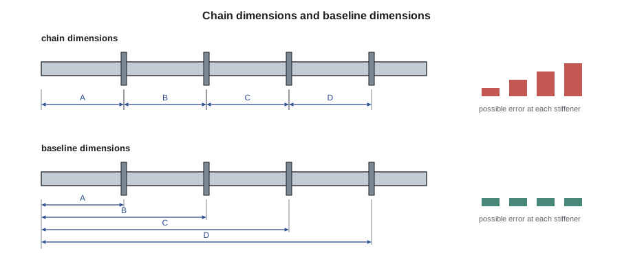
- Chain dimensioning gives each feature's distance from the one before it, like links in a chain. It is easy to read for layout, one step at a time, but every link's error adds to the next, so the last feature in a long chain can be well out of position.
- Baseline dimensioning gives every feature's distance from the same reference, such as one end of a beam or a work point. Errors do not accumulate, because each feature is located independently, but the numbers get large and the fitter must measure from the same reference every time.
- Running or ordinate dimensioning is a compact form of baseline dimensioning: a single line of dimensions all measured from a zero point, written along the line. It is common on long beams with many holes or stiffeners, and on CNC cutting drawings.
Most shop drawings combine them. On the Coldwater base frame, the stiffener positions along each long beam are given as running dimensions from the end of the beam that has the lifting lug, marked as the zero end. The hole pattern in each base plate is chain-dimensioned within the pattern, with the pattern located by a single dimension from the work point. Devon learns to measure stiffener positions with the tape hooked on the zero end, all the way along, rather than moving the tape from stiffener to stiffener.
Tolerances
No dimension can be held exactly. A tolerance says how far the finished part can be from the stated dimension and still be acceptable. Tolerances can be written in several ways:
- As a plus-and-minus value after the dimension, for example 49 1/4 ± 1/8, meaning anything from 49 1/8 to 49 3/8 is acceptable.
- As unequal limits, for example +1/8, −0, when a part may be long but not short.
- As limits, writing the largest and smallest acceptable sizes directly.
- As a general tolerance in a tolerance block or note, which applies to every dimension that has no tolerance of its own.
- By reference to a code or standard, such as the fabrication tolerances in the structural welding code or the steel construction standard for the project.
Structural steel tolerances are set mostly by the construction standard and the code rather than written on every dimension. For example, the length of a member framing into others at both ends must be within a few millimeters, and the straightness, camber and squareness of members have their own limits. Hartwell's general tolerance note on structural shop drawings gives a default for dimensions not otherwise covered, and the drawing calls out tighter tolerances where they matter, such as the spacing of bolt holes that must match equipment.
Machine and equipment drawings often use the geometric dimensioning and tolerancing system, with tolerances on features such as flatness, position and perpendicularity shown in feature control frames, following ASME Y14.5. It is less common on structural shop drawings but appears on machined parts that are welded into a fabrication, such as pump mounting pads.
On the Coldwater skid, the pump and motor mounting pads are a case in point. The pads are welded to the base frame and then machined flat, and the drawing gives a flatness tolerance of 0.004 in across both pads after machining, shown in a feature control frame. The welder's job is to get the pads close enough to level that the machinist can clean them up without cutting through.
How tolerances add up
When several pieces are fitted together, their tolerances add up. If a frame is made of three pieces end to end, each ±1/16 in, the overall length could be off by 3/16 in in the worst case if every piece were at the same limit. This is called a tolerance stack-up. The worst-case stack is simply the sum of the individual tolerances.
In practice, it is unlikely that every piece will be at its worst limit in the same direction. If the errors are random and independent, a statistical estimate called the root sum of squares gives a more practical idea of the overall error that will usually be seen:
The worst case is what must be designed for when the parts must always fit. The root sum of squares is what a shop can expect most of the time when the errors are random. Weld shrinkage is not random, though: every weld shrinks in the same direction, so a frame with many welds tends to come out short, and that has to be allowed for separately, as the course on welding metallurgy described.
# Tolerance stack-up along the Coldwater base frame: worst case and root sum of squares
import math
pieces = [  # name, tolerance (plus or minus, in)
    ("end plate thickness", 0.02),
    ("cross member b3 length", 0.0625),
    ("cross member b4 length", 0.0625),
    ("cross member b5 length", 0.0625),
    ("gap at each fit-up (x4)", 0.0625),
    ("end plate thickness", 0.02),
]
tols = [t for _, t in pieces]
worst = sum(tols)
rss = math.sqrt(sum(t ** 2 for t in tols))
print(f"worst case stack:     +/-{worst:.3f} in")
print(f"root sum of squares:  +/-{rss:.3f} in")
allowed = 0.25
print(f"allowed on overall length: +/-{allowed} in")
print("worst case fits" if worst <= allowed else "worst case can exceed the allowance: control the fit-up or the pieces")
print("typical (RSS) result fits" if rss <= allowed else "even the typical result can exceed the allowance")worst case stack: +/-0.290 in root sum of squares: +/-0.128 in allowed on overall length: +/-0.25 in worst case can exceed the allowance: control the fit-up or the pieces typical (RSS) result fits
The calculation tells Devon two things. In the worst case the frame could be just outside the allowance on its overall length, but it will usually be well inside. The biggest contributors are the cross member lengths and the fit-up gaps, which are the things the fitter controls. If he cuts the cross members to the middle of their tolerance and holds the gaps tight, the frame will come out within the allowance every time.
General notes
Every shop drawing has a block of general notes, usually above the title block. They apply to everything on the drawing unless a view or symbol says otherwise, and they often carry more weld information than all the symbols put together. A typical set of general notes on a Hartwell structural drawing covers:
- Units and default tolerances.
- Material: the default grade for plate, shapes and pipe, and any special requirements such as toughness testing or through-thickness properties.
- The code: for example, welding to CSA W59 or AWS D1.1, with the year or edition specified by the contract.
- Default welds: for example, all fillet welds 1/4 in unless noted, or all shop welds continuous unless noted.
- Weld procedures: welding to approved procedures, with the procedure referenced on the weld map or in the welding symbol tail.
- Edge preparation and finishing: grind sharp edges, remove all slag and spatter, grind flush where noted.
- Inspection and testing: the default visual inspection, and the extent of other testing, such as a percentage of groove welds to be ultrasonically tested.
- Surface preparation and coating: blast standard, primer, paint system, and areas to be masked, such as faying surfaces of bolted connections.
- Marking and shipping: how pieces are marked, and how assemblies are to be supported for shipping.
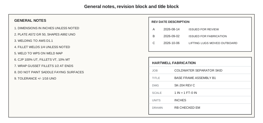
Devon reads the notes on SK-204 twice. Note 4 says all fillet welds not otherwise dimensioned are 1/4 in. Note 6 says all complete joint penetration groove welds are to be ultrasonically tested, and all fillet welds visually inspected. Note 8 says the faying surfaces of the bolted vessel saddle connection are not to be painted. Note 9 gives the default tolerance on dimensions without a tolerance of their own. None of these appear on the views.
Notes on the views
Local notes are attached to a particular feature by a leader, a thin line with an arrow or dot at the end. They say things that apply only to that place, such as drill 7/8 in diameter, 4 holes, or grind flush, or weld after vessel set. A flag note is a number in a small triangle or flag that refers to a note in the general notes list, used when the same note applies in many places. Typical notes such as typical, typ or similar mean the same feature or weld repeats at other places that look the same. Typical saves the detailer drawing the same thing many times, but it puts the job of finding all the other places on the fitter. Devon counts the typical gusset welds on the base frame and gets eight; Raj's weld map lists eight. If the counts had disagreed, that would have been a question for the office.
Abbreviations
Fabrication drawings use many abbreviations. The core blueprint course covered general ones; some that appear often on welded work are:
| Abbreviation | Meaning |
|---|---|
| CJP / PJP | Complete joint penetration / partial joint penetration |
| FW, SW | Field weld, shop weld |
| NS, FS, BS | Near side, far side, both sides |
| EQ SP | Equally spaced |
| TYP | Typical, repeats at similar places |
| UNO | Unless noted otherwise |
| WP | Work point |
| T.O.S. | Top of steel |
| OPP HAND | Opposite hand, a mirror-image part |
| NDE, NDT | Nondestructive examination, nondestructive testing |
| WPS | Welding procedure specification |
Reading a dimension string on the floor
On the first morning Devon lays out the stiffener positions on beam b1, Marta watches how he handles the tape. He hooks it on the zero end, the end with the lifting lug, and checks that the hook is seated against the cut face, not against the burr left by the saw. He reads each running dimension off the tape and marks it with a fine soapstone tick and a square across the flange, and he writes the stiffener mark beside each tick. At the far end, he checks the last running dimension against the overall length of the beam on the drawing. The difference is the error in his layout plus the error in the beam length, and both are inside the tolerance.
Marta then makes him lay out beam b2 the wrong way, chaining from stiffener to stiffener with the tape moved each time, to see what happens. Over six moves, his ticks drift 3/16 in from the running-dimension layout, mostly from reading the tape from a slightly different spot on the soapstone line each time. Nothing about the drift is careless. It is exactly what the chain stack-up predicts, and it is why the drawing gives running dimensions in the first place.
The same thinking applies to holes. A bolt pattern that must match a pump base is dimensioned within the pattern, and the pattern is located by one dimension from a work point. Devon lays out the pattern as a group, from its own center lines, then places the group. If he laid out each hole from the end of the beam, the holes would each be within tolerance but the pattern might not fit the pump.
Common mistakes
MistakeMoving the tape from stiffener to stiffener on a running dimension string.
InsteadHook the tape on the zero end and read each running dimension from it.
MistakeAssuming the worst-case stack-up will never happen.
InsteadDesign fit-up and cutting so that even the worst case is acceptable where parts must fit.
MistakeSkipping the general notes because the views have weld symbols.
InsteadDefault sizes, codes, testing and coating exclusions are often only in the notes.
MistakeTreating typical as one place.
InsteadFind and count every place the typical feature applies.
MistakeConverting units at the bench from a supplier drawing.
InsteadAsk the office to put converted dimensions on the shop drawing.
Summary and key terms
- Canadian drawings are dimensioned in millimeters; US drawings in feet, inches and fractions.
- Chain dimensions let errors accumulate; baseline and running dimensions locate each feature from one reference.
- Tolerances are shown on dimensions, in a general tolerance note, or by reference to a code or standard.
- Worst-case stack-up is the sum of tolerances; the root sum of squares estimates the usual result when errors are random.
- Weld shrinkage is systematic, not random, and must be allowed for separately.
- General notes carry default welds, codes, inspection, coating and tolerances that apply across the drawing.
- Chain dimensioning
- Dimensioning each feature from the previous one.
- Baseline dimensioning
- Dimensioning every feature from one common reference.
- Tolerance
- The permitted variation from a stated dimension.
- Tolerance stack-up
- The combined effect of the tolerances of several parts fitted together.
- Root sum of squares
- A statistical estimate of a stack-up, the square root of the sum of the squared tolerances.
- General notes
- Notes that apply to the whole drawing unless overridden locally.
Practice problems
Work each problem on paper first, then reveal the answer to check.
Four parts each ±1/16 in are fitted end to end. What is the worst-case stack?
Show answer
4 x 1/16 = ±1/4 in.
What is the root sum of squares for the same four parts?
Show answer
√(4 x 0.0625²) = 0.125, or ±1/8 in.
What does UNO mean in a note?
Show answer
Unless noted otherwise.
Lesson quiz · 5 questions
Score 60% or more to complete this lesson.
Create a free account to save your progress, take quizzes and earn a certificate.