
WLD-220 · Lesson 2 of 12 · 17 min
Views, sections and details on weld drawings
A weld lives in a joint, and a joint is a three-dimensional thing: two or more pieces meeting at an angle, with edges that may be cut, beveled or left square. A drawing is flat. The way a flat drawing shows a three-dimensional joint is through views: the same object seen from different directions, cut open along a line to show its inside, or blown up to show a small area at a larger scale. The core blueprint reading course covered orthographic and isometric views in general. This lesson looks at how they are used on welded fabrication drawings, where the most important information, the shape of the joint and the location of the weld, is often visible only in one view, one section or one detail. It also covers scale, and why a welder should never measure a drawing with a tape.
Orthographic views on shop drawings
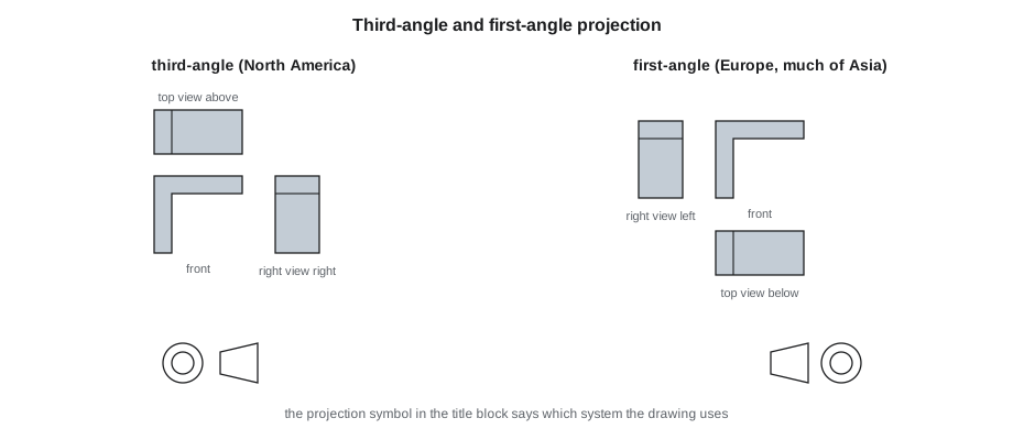
Most shop drawings use orthographic projection: the object is drawn as seen looking straight at each face, with the views arranged so that they line up with each other. North American drawings use third-angle projection. The front view is the main view; the top view is drawn above it, the right side view to its right, and so on, each view showing what you would see if you walked around to that side and looked at the object. Lines that project from one view to the next line up, so a hole in the front view lines up with the same hole in the top view.
European and many Asian drawings use first-angle projection, in which the views are arranged the other way: the top view is drawn below the front view and the right side view to its left. A projection symbol, a small truncated cone drawn in the title block, tells you which system the drawing uses. Hartwell receives first-angle drawings from time to time for equipment bought from European suppliers, such as the separator vessel internals on the Coldwater skid, and Raj tells every new fitter to check the symbol before assuming which side is which.
Shop drawings rarely show all six possible views. A long beam might be drawn in elevation, looking at its side, with an end view and a top view only where there is something to show, such as holes in the flange or a stiffener on the far side. Each view is labeled when it is not obvious, for example elevation, plan, end view or view A.
Visible lines, hidden lines and center lines
Welding drawings use the standard line types. Visible edges are thick continuous lines. Hidden edges, such as a stiffener on the far side of a web, are dashed lines. Center lines, made of alternating long and short dashes, mark the centers of holes, the axes of pipes and the working lines of members. Dimension and extension lines are thin. A phantom line, long dash and two short dashes, shows an adjacent part that is not part of this drawing, such as the vessel that will sit on the base frame, or an alternative position.
Hidden lines matter more on weld drawings than on many others. A weld on the far side of a joint is often shown in a view where the joint itself is hidden, and the welding symbol arrow may point to a dashed line. The symbol rules, covered later in the course, say which side of the joint the weld goes on. The view tells you which physical side of the piece that is.
Section views
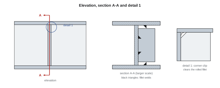
A section view shows what the object would look like if it were cut through along a line and the front part removed. The cutting plane line on the main view, a thick line with arrows at its ends, shows where the cut is and which way you are looking, and the letters at the arrows name the section, for example section A-A. The section itself is drawn elsewhere on the sheet, often at a larger scale, with the cut surfaces filled with thin diagonal hatching.
Sections are the most useful views on a weld drawing because they show the joint in cross-section, which is how a welder thinks about it: the edge preparation, the root opening, the fit-up of the pieces and the size and shape of the finished weld. A fillet weld is a triangle in section; a groove weld fills the space between beveled edges. Many drawings show the weld itself filled in solid black or shaded in the section.
Sections come in several forms. A full section cuts all the way through. A half section cuts through half of a symmetrical part to show the inside and outside in one view. A revolved section is drawn on top of the view, rotated into the plane of the drawing, often used to show the cross-section of a bar or a rib. A removed section is drawn away from the view, labeled with its letters. A broken-out section cuts away only a small area to show a hidden feature, such as a weld inside a box.
Details
A detail is an enlarged drawing of a small area. On the main view, a circle or cloud surrounds the area, with a label such as detail 1 or detail B; the detail itself is drawn elsewhere at a larger scale, such as twice or five times the scale of the main view. Details are used for anything too small to show clearly at the main scale: corner clips on stiffeners, weld access holes in beams, the edge preparation of a groove weld, the weep holes in a base plate, or the layout of a lifting lug.
Standard details that apply to many places on a job are often drawn once on a typical details sheet, and the welding symbol or a note refers to them, for example see typical detail TD-4. On the Coldwater skid, the corner clip for every stiffener and gusset is drawn once, with a note that all stiffeners are clipped 1 in at the corners unless shown otherwise. The clip lets the stiffener clear the radius where the beam web meets the flange and stops the stiffener welds from running into the fillet of the rolled shape.
Reference marks: finding the section and detail
On a multi-sheet package, a section or detail is often drawn on a different sheet from the view that calls it out. The callout symbol then has two parts: the section or detail name, and the sheet it is drawn on. A bubble with A over SK-204, for example, means section A is drawn on sheet SK-204. On the sheet where the section is drawn, its title usually says where it was taken from. Following these references back and forth is a routine part of reading a weld drawing, and the core course called them reference marks. On a welded assembly, a weld symbol will sometimes refer to a detail for the joint preparation, so the welder has to follow two references: the symbol to the detail, and the detail to the procedure.
Isometric and pictorial views
Isometric views show the object in three dimensions, with all three axes drawn at equal angles. They are easier to understand at a glance than orthographic views and are common on pipe spool drawings, where the spool is shown as a single line with fittings, welds and dimensions marked along it. Many structural shop drawings now include a small isometric view of each assembly, generated by the detailing software, to help the fitter see how the pieces go together.
Isometric views are a guide, not a source of dimensions for welded steel. The dimensions and weld information on a structural assembly drawing are given on the orthographic views and sections. On pipe spool isometrics, the dimensions are given along the lines between fittings and welds, and the welds are numbered for the weld map. Hartwell's Unit 4 spools arrive as isometrics, one sheet per spool, with every field weld marked FW and every shop weld numbered.
Scale
The scale of a drawing is the ratio between the size on paper and the real size. The scale of each view is given in the title block or under the view title. Shop drawings for structural steel and plate work commonly use scales such as 1:10, 1:20 or 1:5 in metric, and 1 in = 1 ft-0 in, 3/4 in = 1 ft-0 in or 1-1/2 in = 1 ft-0 in in imperial. Details may be at 1:2 or full size. Pipe isometrics are often not to scale at all, marked NTS.
US shop drawings are dimensioned in feet and inches, and the scale is written as a relation such as 1 in = 1 ft-0 in, meaning 1 in on paper is 12 in on the steel, a ratio of 1:12.
Drawings are made to scale so that they look right, not so that they can be measured. A print may have been reduced to fit a smaller sheet, the paper may have shrunk, or the view may have been drawn out of scale to fit, with a wavy line or a note to show it. The dimensions written on the drawing govern. Raj tells every fitter the same thing: if a dimension you need is not on the drawing, ask for it. Do not scale it.
There are times when scaling is useful as a check. If a dimension written on the drawing looks wrong, a quick measurement of the view with a scale rule can show whether it was mistyped or whether the view is out of scale. A dimension marked NTS, not to scale, or underlined, has been drawn at a different size from what it says.
# Scale conversions: what a measurement on a print means, and why the written dimension governs
scales = [("1 in = 1 ft-0 in", 12), ("1/2 in = 1 ft-0 in", 24), ("3 in = 1 ft-0 in", 4)]
def real(measured, scale):
    return measured * scale
# A print measured with a rule, at three possible scales (if the print was resized, all three are wrong)
measured = 2.5        # in on paper
for name, sc in scales:
    print(f"{measured} in on paper at {name:22} -> {real(measured, sc):7.0f} in on the steel")
# The same view printed on a smaller sheet: half-size reduction
print()
print("printed at half size, the same feature measures", measured / 2, "in")
print("read at the original scale it would be", real(measured / 2, scales[0][1]), "in: wrong by half")2.5 in on paper at 1 in = 1 ft-0 in -> 30 in on the steel 2.5 in on paper at 1/2 in = 1 ft-0 in -> 60 in on the steel 2.5 in on paper at 3 in = 1 ft-0 in -> 10 in on the steel printed at half size, the same feature measures 1.25 in read at the original scale it would be 15.0 in: wrong by half
The calculation is easy; the danger is in the assumptions. A view that measures 2.5 in on paper could be 30 in, 60 in or 10 in depending on its scale, and half of any of those if the sheet was printed at half size. The written dimension removes all the doubt.
Working lines and work points
Structural drawings locate members by working lines and work points rather than by their edges. A working line is usually the center line of a member, such as the center of a pipe or the center of gravity line of an angle, and a work point is where working lines meet. Dimensions are given from work point to work point, and the pieces are located relative to them. On the Coldwater base frame, the work points are the intersections of the beam center lines, and the corner gussets are located by their distance from those points. A fitter who measures from the edges of the beams instead of the center lines will place every gusset half a flange width off.
Putting a joint together from several views
To understand one weld, a welder often needs three things from three places: the view that shows where the joint is, the section that shows its shape, and the symbol that says what weld to make. On sheet SK-204, the gusset at each corner of the base frame is shown in plan, where its position is dimensioned from the work point; in section C-C, which shows that the gusset sits on the top flange of the long beam and against the web of the cross member; and in detail 3, which shows the corner clip and the bevel on one edge. The welding symbols on section C-C say what welds to make on each edge. Devon reads all three before he lays out the first gusset, and he marks the bevel side on the steel with soapstone so that the burner and the fitter both see it.
Common mistakes
MistakeAssuming a drawing is in third-angle projection without checking.
InsteadLook for the projection symbol in the title block, especially on supplier drawings.
MistakeMeasuring a missing dimension off the print.
InsteadAsk for the dimension; prints are not reliable for scaling.
MistakeReading a section view as if you were looking the other way.
InsteadThe arrows on the cutting plane line show the direction of view.
MistakeMeasuring member locations from flange edges.
InsteadLocate from the working lines and work points shown on the drawing.
MistakeTaking dimensions from a pipe isometric drawn not to scale.
InsteadUse only the dimensions written along the lines.
Summary and key terms
- North American drawings use third-angle projection; the title block symbol says which system applies.
- Hidden lines and center lines carry important weld and location information.
- Section views show joints in cross-section, including edge preparation and weld shape.
- Details enlarge small areas; reference marks say which sheet a section or detail is on.
- Isometrics help with understanding but do not replace dimensioned views on structural work.
- Written dimensions govern; drawings must not be scaled to find a dimension.
- Members are located from working lines and work points.
- Third-angle projection
- The view arrangement used in North America, with the top view above and the right view to the right of the front view.
- Section view
- A view of the object as if cut along a cutting plane, with cut surfaces hatched.
- Cutting plane line
- A thick line with arrows that shows where a section is cut and the direction of view.
- Detail
- An enlarged view of a small area, called out on the main view.
- Work point
- A reference point where working lines of members meet, used to locate members.
- NTS
- Not to scale.
Practice problems
Work each problem on paper first, then reveal the answer to check.
A view is drawn at 1 in = 1 ft-0 in. A feature measures 1-3/4 in on the print. What does it represent?
Show answer
1.75 x 12 = 21 in, but use the written dimension if there is one.
Where is the top view placed in third-angle projection?
Show answer
Above the front view.
What does a callout reading B over SK-206 mean?
Show answer
Section or detail B is drawn on sheet SK-206.
Lesson quiz · 5 questions
Score 60% or more to complete this lesson.
Create a free account to save your progress, take quizzes and earn a certificate.