
RCDD-115 · Lesson 5 of 12 · 24 min
High-density fiber and modular cabling
▶ Video coming soon A video version of this lesson is on the way.
Tomasz Wiercinski, the cabling contractor's foreman, stops by Lakehead Signal's office with a sample in a plastic bag: a thin, flat fiber trunk with a rectangular connector on each end. 'Your spec says field-terminated LC everywhere in the data room,' he says. 'For two hundred and forty fibers, that's a lot of splicing in a small room with the servers arriving in six weeks. Have you thought about pre-terminated?' Daniel had not. Roz had, and had been waiting for him to ask. 'Good,' she says. 'Today we find out why data centers stopped splicing.'
Data centers need far more fiber in far less space than any other part of a building, and they need it installed quickly, tested reliably and changed often. Two developments make this possible: array connectors that terminate many fibers at once, and modular, factory-terminated cabling that is plugged together on site rather than built there. This lesson explains both, along with the polarity rules that keep transmitters connected to receivers, and the density and loss trade-offs a designer must check.
Array connectors
An MPO connector, short for multi-fiber push-on, holds a row or rows of fibers in a single rectangular ferrule. The common types hold 8, 12, 16 or 24 fibers; larger counts exist for special uses. A single MPO connector takes up about the same space as one duplex LC connector but carries six or twelve times as many fibers. Alignment is done with two precision guide pins on one connector, called the male or pinned connector, that fit into holes on the other, the female or unpinned one. Two MPO connectors mated together must be one of each.
MPO connectors are used in two ways. As trunk connectors, they join pre-terminated trunk cables to cassettes or breakout modules, which convert them to duplex LC or other connectors at the patch panel. As equipment connectors, they plug directly into parallel optic transceivers, which send and receive on several fibers at once. A 400 gigabit short-reach interface, for example, may use eight fibers: four to transmit and four to receive, each at 100 gigabits per second.
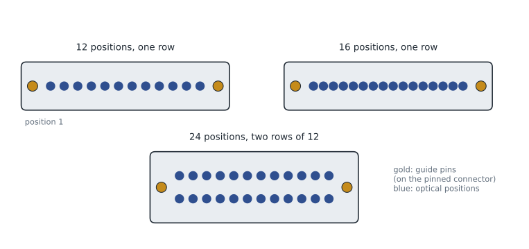
Very small form factor connectors
Newer duplex connectors, often called very small form factor connectors, fit two or more duplex connections into the space of one LC duplex. They let designers put more individually patchable ports in a panel and are designed for transceivers that split one high-speed port into several lower-speed ones. Their names are trademarks of their makers, and the designer should specify them by performance and compatibility rather than by brand alone unless the owner has standardized on a product.
Pre-terminated trunks and cassettes
A pre-terminated trunk is a fiber cable cut to length and terminated with connectors in a factory, then tested and shipped with a test report. On site, it is pulled into place and plugged in. Cassettes, also called modules, sit in patch panels and contain short factory-assembled harnesses that connect an MPO trunk at the rear to duplex connectors at the front. Some systems skip the cassette and use MPO adapter panels, with MPO-to-duplex harnesses at the equipment.
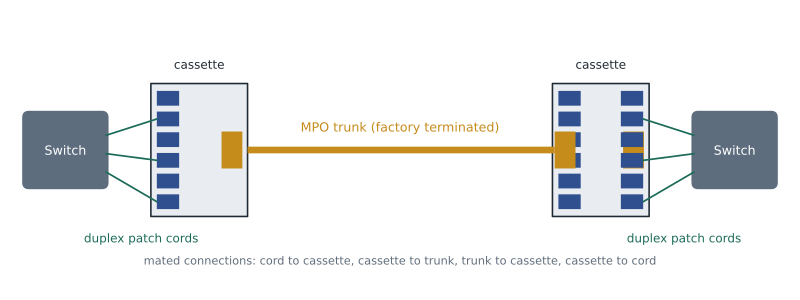
Pre-terminated systems have clear advantages in data centers. Installation is fast, with no field polishing or splicing. Factory termination gives lower and more consistent loss than most field work. Trunks can be replaced or moved without disturbing nearby cables. And the system is easier to change: when the network moves from duplex to parallel optics, the cassettes can be swapped for MPO adapter panels while the trunks stay. The disadvantages are that every trunk must be measured and ordered to length before installation, lead times can be several weeks, and a trunk damaged on site must usually be replaced rather than repaired.
Lengths matter. A trunk that is too short cannot be stretched; one that is far too long leaves coils that fill trays and cabinets. Designers measure each route along the actual pathway, including the rise into each cabinet and the slack needed for future movement, and add a small allowance. Many contractors walk the route with a measuring wheel or use a three-dimensional model of the trays once they are installed, then order trunks.
Worked problem
Ordering a trunk
A trunk runs from cabinet 7 to the network row. The tray route is 14.2 m long. Each end needs 1.8 m to drop from the tray into the cabinet and reach the panel, and the owner wants 1.0 m of slack stored at each end. What length should be ordered, rounded up to the next half meter?
Show solution
- Tray route: 14.2 m.
- Drops: 2 × 1.8 = 3.6 m.
- Slack: 2 × 1.0 = 2.0 m.
- Total: 14.2 + 3.6 + 2.0 = 19.8 m, rounded up to 20.0 m.
Answer: 20.0 m. Ordering from measured routes avoids both short trunks and large coils of excess cable.
Fiber counts and utilization
The number of fibers per connector should match the applications. Parallel optics that use eight fibers fit neatly on 8-fiber or 16-fiber connectors, or on 24-fiber trunks split three ways into 8-fiber groups. When an 8-fiber application runs over a 12-fiber MPO connector, four of the twelve fibers are unused, a third of the installed fiber. Systems built in groups of 8 or 16, often called base-8 and base-16, avoid this waste for those applications, while base-12 and base-24 systems match duplex breakouts of six or twelve ports. The designer should ask the network team which interfaces they expect in the next five to ten years and choose a base that wastes the least.
Worked problem
Utilization of a base-12 trunk
A 24-fiber MPO trunk serves a cabinet whose leaf switch uses 8-fiber parallel optic uplinks. How many uplinks can it carry, and how many fibers are left unused, if the system uses two 12-fiber connectors at each end? What if the trunk uses one 24-fiber connector broken out into three 8-fiber groups?
Show solution
- With two 12-fiber connectors, each connector carries one 8-fiber uplink, leaving 4 fibers unused on each.
- Uplinks: 2; unused fibers: 2 × 4 = 8, a third of the trunk.
- With three 8-fiber groups from a 24-fiber trunk: 3 uplinks, no unused fibers.
Answer: Two uplinks with 8 fibers unused in the base-12 arrangement; three uplinks with none unused in a base-8 arrangement.
Polarity
Every fiber link must connect a transmitter at one end to a receiver at the other. With duplex patch cords this is easy to see and easy to fix by flipping a connector. With MPO trunks and cassettes, the fibers cross over inside components where nobody can see them, so the designer must choose a consistent polarity method for the whole system. The fiber component standard, ANSI/TIA-568.3, describes three methods, called A, B and C, which differ in how fiber positions are arranged inside the trunk and which type of patch cords is used at each end.
| Method | Trunk arrangement | What changes at the ends | Practical note |
|---|---|---|---|
| A | Straight through: position 1 to position 1 | One end uses a standard patch cord, the other a crossover cord | Two cord types to stock; simple trunks |
| B | Reversed: position 1 to position 12 | Same cord type at both ends; cassettes or adapters arranged to suit | Common in parallel optic systems |
| C | Pairs flipped: 1 to 2, 2 to 1 and so on | Standard cords at both ends for duplex; not suited to parallel optics | Less common in new designs |
The practical rule is to pick one method, document it in the specification, buy every component from a system whose parts are designed for that method, and label cassettes and trunks accordingly. Mixing methods is the most common cause of links that test perfectly for loss but carry no traffic.
Density and its limits
A 1U patch panel with duplex LC adapters typically holds 48 duplex ports, or 96 fibers. With cassettes and MPO trunks the same space may hold 144 fibers, and with very small form factor connectors or MPO adapter panels much more. High density saves cabinet space, which is valuable in a data center, but it has limits. Technicians must be able to reach, identify and remove one cord without disturbing its neighbors, so density gains are only useful if the panels, cord management and labeling make that possible.
Worked problem
Panel space
The Harbourview network row must terminate 10 trunks of 24 fibers each, plus two 144-fiber backbone cables from the entrance room. Each 1U panel holds four cassettes, and each cassette terminates 24 fibers. How many rack units of panels are needed?
Show solution
- Fibers from cabinets: 10 × 24 = 240.
- Fibers from the entrance room: 2 × 144 = 288.
- Total fibers: 240 + 288 = 528.
- Fibers per 1U panel: 4 × 24 = 96.
- Panels: 528 ÷ 96 = 5.5, rounded up to 6 rack units.
Answer: Six rack units of panels, plus vertical and horizontal cord management. Leaving one or two spare units for growth is wise.
Loss in modular systems
Every MPO-to-cassette transition adds a connection, and each connection uses some of the loss budget. A channel that passes through a cassette at each end of a trunk has at least four mated pairs: duplex cord to cassette, cassette to trunk, trunk to cassette and cassette to duplex cord. As RCDD-110 showed, high-speed multimode applications may allow less than 2 dB for the whole channel, so standard maximum connector loss would not fit. Designers using modular systems specify low-loss components with guaranteed maximum values, add up the channel, and confirm it against the application limit.
Worked problem
Checking a modular channel
A channel has 30 m of OM4, an MPO trunk with a cassette at each end and duplex cords at each cassette. The manufacturer guarantees 0.35 dB per MPO mated pair and 0.15 dB per duplex LC mated pair, and the cassettes include those values. The application allows 1.9 dB at 850 nm. Does it fit?
Show solution
- Fiber: 3.5 dB/km × 0.030 km ≈ 0.11 dB.
- MPO connections: 2 × 0.35 = 0.70 dB.
- Duplex connections: 2 × 0.15 = 0.30 dB.
- Total: 0.11 + 0.70 + 0.30 = 1.11 dB, about 0.8 dB below the limit.
Answer: Yes, with about 0.8 dB to spare. With standard 0.75 dB maximum values for all four connections, the total would be 3.11 dB and the channel would fail.
Cleaning, inspection and testing
High-density connectors are only as good as their end faces. A speck of dust on one fiber of an MPO ferrule can add loss or cause reflections, and on parallel optics a single dirty fiber can take down a whole link. Every connector should be inspected with a microscope or automated inspection probe and cleaned if needed before it is mated, every time. The international end-face inspection standard, IEC 61300-3-35, gives pass and fail criteria, and many owners require inspection images to be saved for a sample of ports.
Factory test reports for pre-terminated trunks do not replace field testing of the installed system, because trunks can be damaged during installation and cassettes can be installed incorrectly. Field certification measures insertion loss and verifies polarity for each channel or link, using test equipment with MPO interfaces or with fan-out cords. RCDD-116 covers testing in detail.
The decision
Roz and Daniel revise the specification. Each cabinet will get a 24-fiber, base-8 compatible, pre-terminated OM4 trunk for today's parallel optic uplinks and a 12-fiber singlemode trunk for the duplex singlemode links the network team expects next. Cassettes in the network row will be low-loss, and the polarity method is written into the specification with a requirement that all components come from one documented system. Tomasz measures the tray routes as soon as the trays are installed, and the trunks are ordered four weeks before the cabinets arrive.
Common mistakes
MistakeOrdering trunks from drawing lengths.
InsteadMeasure installed routes, add drops into cabinets and slack, and then order.
MistakeMixing polarity methods within one channel.
InsteadSpecify one method and use components designed for it throughout.
MistakeForgetting that cassettes add connections.
InsteadCount every mated pair and use guaranteed low-loss values when checking high-speed channels.
MistakeMating MPO connectors without inspection.
InsteadInspect and clean every end face before mating; one dirty fiber can stop a parallel link.
Summary and key terms
- MPO connectors terminate 8, 12, 16, 24 or more fibers in one ferrule, aligned by guide pins.
- Pre-terminated trunks and cassettes install quickly with consistent loss but must be ordered to measured length.
- Base-8 or base-16 systems match eight-fiber parallel optics; base-12 or base-24 systems match duplex breakouts.
- Polarity methods A, B and C keep transmitters connected to receivers; one method must be used throughout.
- Modular channels have more connections, so low-loss components are often needed for high-speed applications.
- End-face inspection and cleaning are essential, and installed systems must be field tested.
- MPO
- Multi-fiber push-on connector holding many fibers in one ferrule.
- Cassette
- A module that converts an MPO trunk at the rear to duplex connectors at the front.
- Pre-terminated trunk
- A factory-terminated and tested multi-fiber cable assembly.
- Parallel optics
- Transceivers that transmit and receive over several fibers at once.
- Polarity
- The arrangement that connects each transmitter to the correct receiver.
- Base-8
- A system organized in groups of eight fibers to match eight-fiber parallel optics.
Practice problems
Work each problem on paper first, then reveal the answer to check.
A 12-fiber MPO carries an 8-fiber application. What share of the fibers is unused?
Show answer
Four of twelve, a third.
A route measures 9.5 m with 1.5 m drops at each end and 1 m of slack at each end. What trunk length is needed?
Show answer
9.5 + 3 + 2 = 14.5 m.
Why can a link pass its loss test but carry no traffic?
Show answer
Wrong polarity: the transmitter is connected to a transmitter instead of a receiver.
Lesson quiz · 5 questions
Score 60% or more to complete this lesson.
Create a free account to save your progress, take quizzes and earn a certificate.