
RCDD-111 · Lesson 6 of 12 · 18 min
Environmental, power and lighting requirements for spaces
▶ Video coming soon A video version of this lesson is on the way.
Daniel's worst summer as an installer was spent in a high school where the telecommunications rooms were cooled by the building's air handlers, which shut down every evening at six and all weekend. By Monday morning the rooms were hot enough that switches had rebooted themselves, and the custodian had propped the doors open with garbage cans to let the heat out. 'The rooms were the right size and in the right place,' he tells Roz. 'They just couldn't keep the equipment alive.' Roz nods. 'Space is only half of a room. The other half is what you feed it: cooling, power and light. And unlike space, you can measure all three.'
This lesson covers the environmental, power and lighting requirements that turn a room into a working telecommunications space. These requirements are shared with other disciplines, because the mechanical engineer designs the cooling, the electrical engineer designs the power and lighting, and the fire protection engineer designs the sprinklers. The ICT designer's role is to state clearly what each room needs, to calculate the loads, and to check that the other disciplines' drawings deliver it. Most failures in telecommunications rooms come not from the cabling but from heat, power problems and water.
Heat: where it comes from
Almost all the electrical power that enters a telecommunications room leaves it as heat. Switches, servers, UPS units and building system controllers convert their power draw into heat, and power over Ethernet adds a twist: the power delivered to phones, wireless access points and cameras is dissipated mostly at those devices out on the floor, but the switch still dissipates its own losses, including the losses in its power supplies. A room with two 48-port switches and a full power over Ethernet load can easily produce more than a kilowatt of heat continuously, day and night, in a space the size of a large closet.
The design starts with a heat load estimate. Sum the expected power draw of every piece of equipment the room will hold, using manufacturers' typical rather than nameplate values where possible, include the growth equipment, and treat the result as the heat to be removed. In the United States, mechanical engineers usually express cooling in British thermal units per hour or tons of refrigeration: one watt is about 3.412 BTU/h, and one ton is 12,000 BTU/h. Give the mechanical engineer the number and its basis, not just the request for 'air conditioning'.
Writing the requirements down
Environmental, power and lighting requirements are easy to agree in a meeting and easy to lose in the drawings. The most reliable approach is a room data sheet for every telecommunications room and equipment room, as lesson 3 described, with a line for each requirement: heat load and its basis, operating hours, temperature and humidity basis, pressure relationship, standby power, UPS runtime, number and type of equipment circuits, convenience receptacles, lighting level, emergency lighting, sprinkler head guards and monitoring points. Each discipline then checks its own drawings against the sheet, and the ICT designer checks them again at each submission. When something changes, such as the owner adding a UPS or a second switch stack, the data sheet changes first and the loads ripple through to the mechanical and electrical designs.
Worked problem
Estimating a telecommunications room heat load
Each Harbourview telecommunications room will hold two 48-port switches. The manufacturer lists a typical system power of 150 W per switch before power over Ethernet, and the switches will deliver a total of 600 W of power over Ethernet to devices on the floor, through power supplies with an efficiency of about 0.9. A small UPS adds about 60 W of losses, and building system controllers about 120 W. What heat load should Daniel give the mechanical engineer, including a growth allowance that multiplies the load by 1.5?
Show solution
- Switch base load: 2 × 150 = 300 W, all dissipated in the room.
- Power over Ethernet: the 600 W delivered to devices is mostly dissipated out on the floor, but the switch power supplies lose about a tenth of the power they convert, so roughly 600 ÷ 0.9 − 600 ≈ 67 W stays in the room.
- UPS losses and controllers: 60 + 120 = 180 W.
- Present load: 300 + 67 + 180 ≈ 547 W. With growth: 547 × 1.5 ≈ 820 W.
- In the units the mechanical engineer uses: 820 × 3.412 ≈ 2,800 BTU/h, or about 0.23 ton, continuous.
Answer: About 820 W of continuous heat with growth, about 2,800 BTU/h.
Cooling: continuous and controlled
The most important cooling requirement is that it is continuous. Telecommunications rooms and equipment rooms run every hour of every day, so their cooling must too. If the building's air handlers shut down at night or on weekends, the rooms need dedicated cooling, or the building system must be designed to keep serving them independently. For critical rooms such as Harbourview's equipment room, which supports clinics, the cooling should be on standby power so it keeps running when the generator is supplying the building.
The standards have traditionally given an operating range for telecommunications rooms of about 64 to 75 °F with relative humidity kept roughly between 30 and 55 on the relative humidity scale. More recent editions point designers toward the environmental classes published by ASHRAE for ICT equipment, which allow a wider recommended range of inlet temperatures, often up to about 81 °F, because modern equipment tolerates more heat and wider ranges save energy. The designer should state which basis applies, and measure temperature at the equipment air inlets rather than at a thermostat on the wall. Rooms should also be kept at slightly positive pressure relative to the corridor, with filtered air, so that dust is pushed out rather than drawn in.
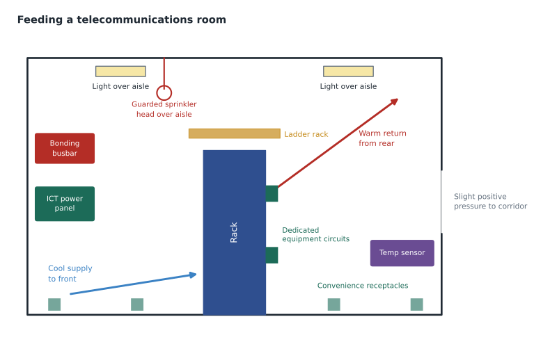
Cooling equipment brings its own risks. In-room cooling units produce condensate, which needs a drain path that does not run over equipment, and leak detection under or around the unit is a sensible precaution. Units should not be mounted directly above racks. Cooling supply and return should be arranged so cool air reaches the equipment intakes and hot exhaust is removed, which in a small room may simply mean placing the supply near the front of the rack row and the return high on the rear side.
Water and fire protection
Fire codes generally require sprinkler protection in telecommunications rooms and equipment rooms, just as in the rest of the building. That puts water pipes above sensitive equipment, so the design minimizes the risk. Sprinkler heads should have wire cages or guards so they cannot be knocked by ladders or cable work, and they should be placed over aisles where possible rather than directly over racks, within the spacing rules of the fire code. Mains and branch lines that do not serve the room should not pass through it. In critical equipment rooms, owners sometimes choose a pre-action system, in which the pipes are dry until a detection system confirms a fire, reducing the risk of a leak or accidental discharge. Gaseous clean-agent systems are used in some data centers but are a specialist subject and need a sealed room.
Drains, washrooms and roofs above the room are the other water risks. The location guidance in lessons 3 and 4 deals with most of them, but where a room cannot avoid a risk, leak detection, drip trays and a raised position for equipment are simple mitigations.
Power: dedicated, protected and planned
Telecommunications rooms need electrical power that is reliable and free from interference by other loads. The usual design provides dedicated branch circuits for equipment, fed from a panel that serves only ICT loads where possible, not shared with lighting, motors or general-purpose outlets in nearby areas. A long-standing guideline is to provide at least two dedicated, non-switched duplex receptacles for equipment, each on its own 20 A, 120 V branch circuit, plus separate convenience receptacles on the walls spaced about 6 ft apart for tools and test equipment. Equipment rooms usually need their own power panel, and modern switch and UPS equipment may need larger or higher-voltage circuits, such as 208 V circuits with locking receptacles, which the electrical engineer sizes from the equipment list.
Critical rooms need standby power. In a building with a generator, the ICT panels should be on the standby system, and the rooms should have UPS protection to bridge the seconds between a utility failure and the generator starting, and to clean up power quality. For Harbourview, the clinic operator wants telephones and wireless to keep working during an outage, so the switches with power over Ethernet must be on UPS, and their UPS runtime becomes part of the design brief. All of this wiring is governed by the National Electrical Code, as adopted locally, and the electrical engineer is responsible for it; the ICT designer supplies the loads, locations and receptacle types.
| Requirement | Typical design practice | Who designs it |
|---|---|---|
| Equipment circuits | At least two dedicated non-switched circuits, often 20 A at 120 V, on separate breakers | Electrical engineer, from ICT loads |
| Convenience receptacles | Separate circuit, receptacles about 6 ft apart on walls | Electrical engineer |
| Panel | Dedicated ICT panel for equipment rooms and larger rooms | Electrical engineer |
| Standby and UPS | Standby power from the generator where available; UPS sized for the bridging or ride-through time the owner requires | Electrical engineer and ICT designer together |
| Bonding | Bonding busbar in each room, connected to the telecommunications bonding backbone | ICT designer and electrical engineer (RCDD-113) |
Lighting
Technicians spend hours reading tiny labels, tracing cables and working at the back of racks, so lighting matters. Telecommunications spaces are commonly specified for about 50 footcandles of illumination, measured about 3 ft above the floor in the working aisles. Fixtures should be placed over the aisles rather than over the racks, where they would be blocked by ladder rack and cast shadows on the front and back of the equipment, and they should be mounted high enough to clear ladder rack and equipment, commonly at least 8.5 ft above the floor. Light-colored walls, ceilings and floors make a large difference to how bright and even the lighting is.
Lighting should not be fed from the same circuits or panel as the ICT equipment, so that a lighting fault does not affect equipment and equipment work does not plunge a technician into darkness. Switches should be just inside the door, and emergency lighting should be provided so technicians are not trapped or left working blind during an outage. Occupancy sensors are acceptable for lighting if they cannot leave a technician in the dark while working quietly behind a rack; many designers set a long time delay or add a manual override.
Other environmental concerns
A few more conditions round out the room environment. Electromagnetic interference from nearby transformers, motors or elevator equipment should be avoided by location, as lesson 3 explained, and RCDD-110 covers the effects. Vibration from mechanical equipment can loosen connections and disturb disk drives over time. Dust and contaminants, including construction dust, are a serious threat to equipment, so rooms should be finished and cleaned before equipment is installed, and ventilation filters should be maintained. Acoustics matter if the room is near offices or classrooms, because fans in switches and cooling units are loud. And the room must be secure, as lesson 3 described for equipment rooms.
Finally, environment must be monitored. A temperature and humidity sensor in each telecommunications room, reporting to the network management system or the building automation system, costs little and turns a Monday-morning surprise into an alert on Saturday night. Daniel adds a monitoring point to every room on the Harbourview drawings, and notes the alarm thresholds the operator wants.
Common mistakes
MistakeThe building air handlers can cool the telecommunications rooms.
InsteadRooms need cooling every hour of every day; if building systems shut down, provide dedicated or independent cooling.
MistakeSize cooling from the nameplate rating of the equipment.
InsteadUse typical power draw, include growth, and remember that power over Ethernet is mostly dissipated at devices on the floor.
MistakePut lights directly above the racks so the equipment is well lit.
InsteadLights over the aisles avoid shadows and conflicts with ladder rack.
MistakeEquipment receptacles can share circuits with lighting and nearby offices.
InsteadEquipment needs dedicated, non-switched circuits, ideally from a panel serving only ICT loads.
Summary and key terms
- Nearly all power entering a telecommunications room becomes heat, so cooling is sized from an equipment heat load estimate with growth.
- Cooling must run continuously, be independent of building schedules and, for critical rooms, be on standby power.
- Traditional guidance kept rooms within a moderate temperature and humidity range; current practice references ASHRAE classes and measures at equipment inlets.
- Sprinkler heads should be guarded and placed over aisles, foreign pipes kept out and water risks mitigated.
- Provide dedicated non-switched equipment circuits, separate convenience receptacles, a dedicated panel for larger rooms, standby power and UPS where required.
- Light rooms to about 50 footcandles at 3 ft above the floor, with fixtures over the aisles on circuits separate from equipment.
- Monitor temperature and humidity in every room.
- Heat load
- The rate at which equipment releases heat that cooling must remove.
- Sensible cooling
- Cooling that lowers air temperature, as opposed to removing moisture.
- Positive pressure
- Keeping a room's air pressure slightly above its surroundings so dust is pushed out.
- Pre-action sprinkler
- A system whose pipes stay dry until detection confirms a fire.
- Dedicated circuit
- A branch circuit that serves only specified equipment.
- Illuminance
- The amount of light falling on a surface, measured in lux or footcandles.
Practice problems
Work each problem on paper first, then reveal the answer to check.
Why is most power over Ethernet power not counted as heat in the telecommunications room?
Show answer
It is delivered to and dissipated by devices out on the floor; only the switch's own conversion losses stay in the room.
Why should sprinkler heads be placed over aisles?
Show answer
To keep water discharge and accidental damage away from equipment while still protecting the room.
What is the benefit of a temperature sensor in each room?
Show answer
Cooling failures raise an alert immediately instead of being discovered after equipment overheats.
Lesson quiz · 5 questions
Score 60% or more to complete this lesson.
Create a free account to save your progress, take quizzes and earn a certificate.