
RCDD-111 · Lesson 12 of 12 · 19 min
Coordinating spaces and pathways with other disciplines
▶ Video coming soon A video version of this lesson is on the way.
The coordination meeting for Harbourview's design development set takes place around a large screen showing the combined building model. The mechanical engineer's ducts are blue, the sprinkler piping is red, Priya Raman's electrical conduit and lights are yellow, and Daniel's cable tray and telecommunications rooms are green. The software has flagged 214 clashes, places where two systems try to occupy the same space. Marcus Feld, the general contractor's project manager, scrolls through them with weary familiarity. 'Every one of these,' he says, 'is cheaper to fix today than on site. On site, the first trade to arrive wins, and it's never the cable tray.'
This final lesson draws the course together around coordination: how the ICT designer works with architects, engineers, contractors and the owner so that the spaces and pathways designed in the earlier lessons actually get built. Coordination is not a separate design activity added at the end. It runs from the first conversation with the architect to the final as-built drawings, and the RCDD exam treats it as part of the designer's professional responsibility. The lesson ends with a design review of Harbourview that uses every topic in the course.
When decisions are made
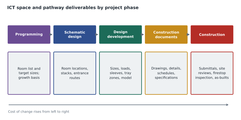
Building projects move through phases, and each phase fixes more of the building. In schematic design, the architect sets the building's shape, cores and major spaces. In design development, systems are sized and located and the disciplines coordinate. In construction documents, the details are drawn and specified for bidding. During construction, the contractor builds from the documents, asks questions through requests for information and submits product data for approval. Each phase makes change harder and more expensive.
Spaces and pathways must be decided early, because they depend on decisions that the architect and structural engineer make early. Telecommunications rooms need to be in the building program before schematic design ends, or there will be nowhere to put them. Backbone sleeves, riser shafts and in-slab conduit must be on the structural drawings before slabs are designed. Entrance conduits must be on the civil drawings before the site is graded. The ICT designer who waits until construction documents to raise these needs will find the building already full.
Who needs what from the ICT designer
Each discipline needs specific information from the ICT designer, and needs it at the right time. The architect needs room sizes, locations, door sizes, finishes, clear heights and which walls must carry backboard, and needs to know which rooms must stack. The structural engineer needs floor loads in equipment rooms and telecommunications rooms, the locations and sizes of sleeves and slots, and any in-slab conduit or poke-through zones. The mechanical engineer needs heat loads and operating hours for every room, the cooling basis, the plenum status of ceilings that the cable specification depends on, and a reserved zone in the ceiling for cable tray. The fire protection engineer needs to know where heads should go relative to racks, and whether the owner wants a pre-action system in the equipment room.
The electrical engineer needs power loads, receptacle types and locations, standby and UPS requirements, lighting levels, the bonding busbar locations and backbone, and the routes of cable tray so that power can be separated from it. The civil engineer needs the entrance conduit routes and maintenance holes. Security, audiovisual, building automation, fire alarm and distributed antenna system designers need outlets, pathways and space in telecommunications rooms. And the owner's IT and facilities staff need to confirm the equipment, growth allowances, security policies and operating requirements that drive everything else.
| Discipline | Needs from the ICT designer | ICT designer needs from them |
|---|---|---|
| Architect | Room sizes, locations, stacks, doors, heights, finishes, backboard walls | Floor plans, cores, rated assemblies and life-safety plans, ceiling types |
| Structural | Floor loads, sleeves, slots, in-slab conduit and coring zones | Slab type, post-tensioning, beam locations, approval of penetrations |
| Mechanical | Heat loads, hours of operation, cooling basis, tray zone in ceilings | Duct routes, plenum designations, cooling equipment and condensate routes |
| Fire protection | Rack locations, head placement requests, pre-action preference | Sprinkler main routes and head locations |
| Electrical | Power loads, receptacles, standby and UPS, lighting, bonding, tray routes | Panel locations, feeder routes, transformer and switchgear locations, conduit types |
| Civil | Entrance routes, conduit counts, maintenance holes | Site utilities, grading, easements, property lines |
| Other low-voltage systems | Outlets, pathways and room space for their equipment | Device counts, locations and power needs |
| Owner IT and facilities | Design options, costs and risks | Equipment lists, growth, security, uptime and operating requirements |
Claiming space in ceilings and shafts
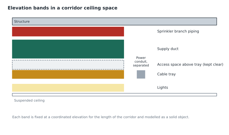
Ceiling coordination works best when each system is given an elevation band in the ceiling space early: for example, sprinkler branches highest near the structure, then ducts, then cable tray at a fixed elevation with its clear access space above it, then lights and ceiling. The bands differ from building to building, but agreeing on them in design development prevents the first trade on site from taking whatever space it likes. In building information modeling, the ICT designer should model cable tray, its access clearance and its required separation from power as solid objects, so that the clash detection sees them, rather than as lines that other models can pass through.
Shafts and cores need the same treatment. Telecommunications room stacks and riser shafts should be labeled in the model as dedicated spaces, with notes that no other services may pass through them. When a clash puts a sprinkler main or a duct through a telecommunications room, the fix is usually to reroute the other service, not to accept it in the room, and the ICT designer has to argue for that with the reasons from lessons 3, 4 and 6.
Separation from power and interference
One coordination topic deserves special mention: separation between telecommunications pathways and electrical power. The electrical code requires minimum separation between communications cables and power conductors for safety, unless barriers or raceways separate them, in Article 800 and related articles of the NEC. The cabling standards add guidance on separation for performance, to limit electromagnetic interference from power cables, transformers, motors and fluorescent lighting. Both depend on what is in the power pathway and how it is enclosed. The practical design rule is to keep telecommunications tray on the opposite side of the corridor from power, cross power at right angles where they must cross, and keep telecommunications rooms away from transformers and switchgear, with the specific distances confirmed with the electrical engineer.
Specifications and drawings
The ICT design is communicated through drawings and specifications that follow the same organization as the rest of the project. In both Canada and the United States, most projects organize specifications using MasterFormat, in which Division 27 covers communications. Spaces and pathways appear in sections such as 27 05 28, pathways for communications systems; 27 05 26, grounding and bonding for communications systems; and 27 11 00, communications equipment room fittings, with firestopping often specified in Division 07 alongside the rest of the building's firestopping. The drawings usually form a telecommunications series of their own, with site plans for entrances, floor plans for outlets and pathways, enlarged plans and elevations of rooms, riser diagrams for the backbone and details for typical installations.
Good documents make coordination visible. The riser diagram shows every sleeve and backbone pathway. Enlarged room plans show racks, ladder rack, sleeves, power and bonding, as lesson 3 described. Pathway schedules list each conduit with its size, route, fill and pull points. And a room data sheet for each space states its requirements in terms the other disciplines can check against their own drawings.
During construction
Coordination continues on site. The ICT designer reviews submittals for tray, conduit fittings, firestop systems, racks and ladder rack to confirm they match the design. Requests for information from the contractor often reveal clashes the model missed, and quick, clear answers keep work moving. Site visits at key stages, such as before slabs are poured, before walls are closed and before ceilings are installed, catch problems while they are still cheap: a missing sleeve, a pull box above a fixed ceiling, a sprinkler head over a rack or a tray buried behind a duct. Firestopping should be inspected before it is concealed. At the end, the designer reviews the as-built drawings and records, because the next designer to work on the building will depend on them.
Working with the owner
Coordination is not only technical. The owner pays for the building and decides how much risk to accept, so the ICT designer must explain choices in terms the owner can weigh: what a smaller room saves now and what it costs at the next refresh, what diversity costs and what an outage would cost the clinics, what re-enterable firestop devices add to the budget and what they save in future cable work. Short written options with costs and consequences let owners make decisions that stick, and those decisions protect the design when someone later proposes to cut it.
Worked problem
The Harbourview design review
Before the construction documents are issued, Roz asks Daniel to review the coordinated model for spaces and pathways and to list the issues he would raise. He finds these: a sprinkler main crossing telecommunications room A on the third floor; the fourth-floor room B shifted 6 ft east of the rooms below because a tenant wanted a larger meeting room; a supply duct sitting in the tray's access zone along the second-floor corridor for 40 ft; a pull box above the fixed plaster ceiling of the lecture hall; the corridor tray passing continuously through the clinic's smoke barrier; and the equipment room cooling on a unit that shuts down with the building's schedule. How should each be resolved?
Show solution
- Sprinkler main in room A: ask the fire protection engineer to reroute the main outside the room; only the branch serving the room's own heads, with guarded heads over the aisle, belongs there (lessons 4 and 6).
- Room B offset on the fourth floor: explain the cost of a horizontal backbone offset and ask the architect to restore the stack, offering to rotate the room within the stack footprint to give the tenant some area (lessons 4 and 5).
- Duct in the tray access zone: ask the mechanical engineer to lower or reroute the duct over the 40 ft, or move the tray within its elevation band, so the agreed clearance above the tray is restored (lessons 8 and 12).
- Pull box above the fixed ceiling: move it to the accessible corridor ceiling before the lecture hall, adjusting the section lengths and bends to stay within the rules (lessons 7 and 10).
- Tray through the smoke barrier: stop the tray on each side and specify a group of listed re-enterable devices with the required ratings, sized for growth (lesson 11).
- Equipment room cooling: require dedicated cooling that runs continuously, on standby power, sized from the equipment heat load (lessons 3 and 6).
Answer: Six issues, each resolved by applying a rule from this course and sending a clear request, with reasons, to the discipline responsible.
The designer's responsibility
The RCDD credential exists because ICT infrastructure has become as essential to a building as power and water, and someone must take professional responsibility for designing it well. In spaces and pathways, that responsibility is mostly exercised through other people: the architect who gives the room its place, the engineer who cools and powers it, the contractor who builds it and the owner who pays for it. The designer's tools are calculations, clear documents and well-timed requests, backed by the codes and standards.
At the end of the project, Daniel walks Harbourview with Tomasz before the ceilings close. The telecommunications rooms stack straight up through the building, the tray runs clear in its band, the sleeves are aligned and capped with re-enterable devices, and the pull boxes are where he can reach them. 'Same room, same place, every floor,' Tomasz says, grinning. Roz, behind them, adds the line she saves for the end of every project: 'Now the cable has somewhere to live.'
Common mistakes
MistakeSpaces and pathways can be finalized in construction documents.
InsteadRooms, stacks, sleeves and entrances depend on early architectural, structural and civil decisions, so they must be settled in programming and schematic design.
MistakeDraw cable tray as a line in the model.
InsteadModel tray, its access clearance and its separation as solid objects so clash detection sees them.
MistakeWhen a sprinkler main crosses a telecommunications room, accept it if it is high enough.
InsteadReroute foreign services out of the room; only services serving the room belong in it.
MistakeThe designer's job ends when the drawings are issued.
InsteadSubmittal review, answers to questions, site reviews, firestop inspection and as-built records are part of the work.
Summary and key terms
- Coordination runs from programming to as-built records; spaces and pathways must be decided earliest.
- Each discipline needs specific information from the ICT designer at the right phase, and the ICT designer needs information from each of them.
- Agree elevation bands in ceilings, reserve shafts and rooms as dedicated spaces, and model tray with its clearances.
- Keep foreign services out of telecommunications spaces and separate telecommunications pathways from power.
- Communicate through Division 27 specifications, telecommunications drawings, pathway schedules and room data sheets.
- During construction, review submittals, answer questions, visit at key stages, inspect firestopping and check as-built records.
- The RCDD's responsibility is exercised through calculations, clear documents and well-timed requests to others.
- Clash detection
- Software checking of a combined building model for systems occupying the same space.
- Elevation band
- An agreed range of height in a ceiling space reserved for one system.
- Request for information
- A formal question from the contractor to the design team during construction.
- Submittal
- Product data or shop drawings submitted by the contractor for the designer's review.
- MasterFormat Division 27
- The specification division covering communications systems.
- As-built drawings
- Drawings updated to show what was actually installed.
Practice problems
Work each problem on paper first, then reveal the answer to check.
Why must telecommunications room locations be in the building program?
Show answer
Rooms need space in the floor plan and stacked positions near the core, which are fixed early in schematic design.
Why is a site visit before ceilings close important?
Show answer
It catches inaccessible pull boxes, blocked trays and unsealed penetrations while they are still cheap to fix.
What makes a coordination request effective?
Show answer
It names the problem, cites the rule and the consequence, proposes a fix and goes to the discipline responsible.
Lesson quiz · 5 questions
Score 60% or more to complete this lesson.
Create a free account to save your progress, take quizzes and earn a certificate.