
RCDD-111 · Lesson 4 of 12 · 19 min
Telecommunications rooms and enclosures
▶ Video coming soon A video version of this lesson is on the way.
Tomasz Wiercinski, the cabling foreman, stops by the office with a coffee and a complaint. His crew has just finished a job where every telecommunications room was a different shape: one long and narrow, one with a column in the middle, one with the door opening into the only wall long enough for racks. 'Every floor we had to reinvent the layout,' he says. 'And on the fourth floor the room wasn't above the third-floor room, so the backbone went sideways through two offices.' Daniel laughs, because he has worked on that kind of job too. Roz does not laugh. 'Write that down,' she tells Daniel. 'Same room, same place, every floor. That's the first rule of telecommunications rooms.'
A telecommunications room (TR) is the floor-serving space of the ICT hierarchy. It is where horizontal cables from the work areas of a floor terminate on the horizontal cross-connect, where the access switches for that floor live, and where the backbone from the equipment room arrives. Most buildings have more telecommunications rooms than any other ICT space, so getting their design right, and making it repeatable, has a large effect on cost, schedule and the long-term usefulness of the cabling. This lesson describes what a telecommunications room does and how it should be built, and when a telecommunications enclosure can serve instead. Lesson 5 covers how many rooms a floor needs and how large they must be.
What a telecommunications room does
The core job of a telecommunications room is to be Distributor A: the place where horizontal cabling meets the backbone. In a typical room you find patch panels terminating the horizontal cables from the work areas, patch panels or fiber enclosures terminating backbone cables, and the active equipment that connects them, usually access switches with power over Ethernet for phones, wireless access points and cameras. Increasingly the room also holds equipment for other building systems that ride on the structured cabling: controllers for building automation, access control panels, distributed antenna system remote units, paging amplifiers and audiovisual distribution equipment. Each of these adds equipment, power, heat and cable, and the room has to be planned for them.
A telecommunications room may also act as an intermediate point in the backbone, holding a cross-connect that serves other rooms, and on the floor where the equipment room is located, the equipment room may serve that floor directly. But the principle remains: every work area outlet is cabled back to one distributor in one room, and every room is connected into the backbone.
One per floor, stacked
The standards call for at least one telecommunications room on each floor of a building, located on the floor it serves. Serving a floor from the floor above or below is discouraged, because horizontal cables then have to pass through floor penetrations, the distance limit is consumed by the vertical run and the cabling no longer follows the floor's own layout. Where a floor is large, more than one room is needed, as lesson 5 explains.
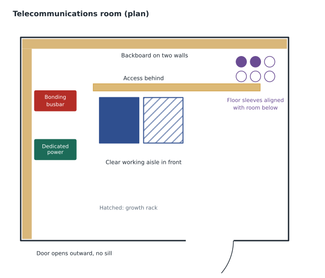
On a multi-story building, telecommunications rooms should be stacked vertically, one above the other, so that the backbone between floors runs straight up through sleeves or slots in the floor, without horizontal offsets. Stacked rooms make the backbone short and cheap, make future additions as simple as pulling a new cable up the stack, and make it easy to firestop and inspect each floor penetration. When the architect proposes moving a room on one floor because a tenant wants the space, the ICT designer should explain what it costs: a horizontal backbone offset through occupied space, extra penetrations, extra firestopping and a weaker backbone for the life of the building.
Where a floor needs more than one telecommunications room, the rooms on the same floor should be connected to each other by a pathway, so that cable can be shared between them, and each stack should have its own backbone path to the equipment room. On Harbourview, Daniel draws two stacks: room A beside the central core and room B in the east wing, each repeated on all four floors.
Building the room
Many of the construction rules for telecommunications rooms are the same as for equipment rooms, scaled to a smaller space. The room should be dedicated to ICT and related low-voltage systems, and should not be shared with electrical panels, janitorial sinks, storage or mechanical equipment. Pipes, ducts and conduits that do not serve the room should not pass through it. The ceiling should give clear height of at least 8 ft, preferably without a suspended ceiling, so that ladder rack and sleeves are visible and reachable. The floor should be sealed against dust, and should carry the room's equipment; a commonly cited minimum for telecommunications rooms is about 50 lbf/ft² of distributed load, with more for heavy equipment such as UPS batteries.
Doors should be at least 36 in wide and 80 in high, without a sill, opening outward or sliding, and lockable. The room needs fire-retardant plywood backboard, commonly 3/4 in thick and 8 ft high, on at least two walls, for wall-mounted equipment and cable management. Walls should be full height to the structure. Lighting, power and cooling follow the rules in lesson 6, and the room needs a bonding busbar connected to the building's telecommunications bonding backbone, covered in RCDD-113.
| Feature | Typical design requirement | Why |
|---|---|---|
| Use | Dedicated to ICT and related low-voltage systems | Security, reliability and space for growth |
| Location | On the floor served, near the center of the area served, stacked with the rooms above and below | Shortest horizontal runs and a straight backbone |
| Clear height | At least 8 ft, preferably with no suspended ceiling | Room for ladder rack and access to sleeves |
| Floor loading | About 50 lbf/ft² distributed minimum, more for heavy equipment | Racks, UPS units and batteries are heavy |
| Door | At least 36 in by 80 in, no sill, opening outward or sliding, lockable | Equipment access and security |
| Backboard | Fire-retardant plywood, about 3/4 in thick and 8 ft high, on at least two walls | Support for wall-mounted equipment and cable |
| Foreign systems | No pipes, ducts or conduits passing through that do not serve the room | Avoid leaks, interference and other trades entering |
Laying out the inside
A small telecommunications room usually holds a single row of racks, set parallel to the longest wall with clear space in front for working and behind for access to the back of patch panels and switches. Racks should be placed so that the ladder rack above them runs directly to the backbone sleeves and to the openings where horizontal cable enters the room, with no sharp turns. Wall-mounted equipment, such as small panels, the bonding busbar and building system controllers, goes on the backboard, kept clear of the rack aisles. The door should open into a wall that is not needed for equipment.
Horizontal cable arrives in large bundles, often several hundred cables per room, and it needs a planned route into the room: through sleeves or a cable tray opening in the wall at ceiling level, down onto the ladder rack and along to the patch panels. The opening must be large enough for the full future count, must keep the cables' bend radius, and, if the wall is a fire separation, must be firestopped with a listed system that allows cables to be added later. Planning these entries is part of the room design, not something to leave for the installer.
Telecommunications enclosures
Not every area justifies a full room. A telecommunications enclosure (TE) is a cabinet or enclosure, generally mounted on a wall or standing in a space, that houses telecommunications equipment, cable terminations and cross-connect cabling for a limited area. The standards allow an enclosure to supplement a telecommunications room, for example to serve a remote part of a floor, a reception area, a small group of classrooms or a security desk, and in some cases to serve as the horizontal distributor for that area. An enclosure is not a substitute for a room on a whole floor of a large building, and it is not the same as a consolidation point, which is a passive connection point within a horizontal cable run.
Because an enclosure sits outside a dedicated room, it needs attention that a room provides automatically: ventilation or cooling for the switches inside, a dedicated power circuit, security so that anyone walking past cannot open it, and a location where technicians can work without moving furniture. Enclosures should not be placed above suspended ceilings or in locations that require a ladder to open, and they should be shown on the drawings with their own pathway back to the telecommunications room or equipment room. They also count against the backbone hierarchy: an enclosure acting as a horizontal distributor is fed by backbone cable like any other Distributor A.
Rooms that change hands
Telecommunications rooms often outlive the organizations that first use them. On Harbourview's office floor, today's tenant may leave in five years and be replaced by two smaller tenants, each wanting its own network. A room designed only for the first tenant's rack count and layout will be crowded and awkward for the next. Designers handle this by planning each room as a standard module: the same rack positions, the same backboard walls, the same sleeve group and the same power and cooling provisions on every floor, with spare rack positions that any future tenant can use. Labels and records also matter, because a new tenant's contractor will arrive with no knowledge of the building's history; ANSI/TIA-606 administration, covered in RCDD-116, gives every room, rack, panel and pathway an identifier that survives changes of tenant.
Worked problem
Room or enclosure for the parking kiosk and security desk?
Harbourview has two small areas far from either telecommunications room stack: a parking payment kiosk at the garage entrance with four outlets, and a security desk in the lobby with twelve outlets, two cameras and an access control panel. The kiosk is outdoors under a canopy; the desk is inside a staffed lobby, 180 ft of cable route from room A. Which should get a telecommunications enclosure?
Show solution
- Security desk: the route from room A is well within the horizontal limit, so the twelve outlets, cameras and panel can be cabled directly to room A. No enclosure is needed, which keeps the active equipment in a secure room.
- Parking kiosk: an outdoor location is unsuitable for a standard enclosure without environmental protection, and four outlets do not justify one.
- For the kiosk, a better design is a single fiber or copper cable in conduit from room A to a small outdoor-rated cabinet provided by the parking equipment vendor, or direct horizontal cabling if the route is within the distance limit.
- Daniel records the decision and the reasons on the design notes so that the owner understands why no enclosures are shown.
Answer: Neither area needs an enclosure: the desk is cabled directly to room A, and the kiosk is served by a protected cable to an outdoor cabinet.
Rooms in multi-tenant buildings
In multi-tenant buildings, such as Harbourview's fourth floor of leased offices, telecommunications rooms come in two kinds. The landlord's rooms, stacked in the core, carry the building backbone, the service provider risers and the building systems. A tenant may build its own room within its leased space to house its own switches and horizontal cross-connect. The design should make the boundary clear: the landlord's room provides backbone and provider connections to each tenant, and the tenant's room serves the tenant's own work areas. Mixing tenant equipment into the landlord's rooms is common in small buildings, but it creates security and access problems, so it should be a deliberate decision with lockable cabinets or cages if it is done.
Whatever the arrangement, Roz's rule holds: same room, same place, every floor. On Harbourview, both stacks are drawn with identical layouts on every floor, so Tomasz's crew will build the same room eight times rather than eight different rooms once each.
Common mistakes
MistakeA floor can be served from the room on the floor below to save space.
InsteadEach floor should have its own room, so horizontal cable stays on the floor and does not consume distance going through the slab.
MistakeRooms only need to be roughly above each other.
InsteadRooms should be stacked so the backbone runs straight up through aligned sleeves, without horizontal offsets.
MistakeA telecommunications enclosure is the same as a consolidation point.
InsteadAn enclosure houses equipment and cross-connects; a consolidation point is a passive connection within a horizontal cable run.
MistakeAn enclosure can go above the ceiling to save floor space.
InsteadEnclosures must be accessible without ladders or moving ceiling tiles, with power, ventilation and security.
Summary and key terms
- The telecommunications room is Distributor A, where horizontal cabling meets the backbone, and it increasingly hosts building system equipment.
- Provide at least one room per floor, on the floor served, and add rooms on large floors.
- Stack rooms vertically so backbone runs straight up through aligned sleeves, and connect rooms on the same floor.
- Build rooms as dedicated ICT spaces with clear height, sealed floors rated for the load, outward doors, backboard on two walls and no foreign systems.
- Plan cable entries, rack rows and ladder rack routes as part of the room design.
- A telecommunications enclosure can serve a limited area but needs power, cooling, security and an accessible location.
- In multi-tenant buildings, separate the landlord's backbone rooms from tenant rooms or secure tenant equipment.
- Telecommunications room
- A floor-serving space that houses the horizontal cross-connect and related equipment.
- Telecommunications enclosure
- A cabinet that houses equipment and terminations for a limited area.
- Stacked rooms
- Rooms placed directly above each other so backbone pathways run vertically.
- Consolidation point
- A passive connection point within a horizontal cable run in open areas.
- Backbone sleeve
- A short conduit through a floor that carries backbone cable between stacked rooms.
- Landlord room
- A shared room in a multi-tenant building carrying the building backbone and provider risers.
Practice problems
Work each problem on paper first, then reveal the answer to check.
Why is serving a floor from the room below discouraged?
Show answer
The horizontal cable must pass through the slab, using up distance and penetrations, and no longer follows the floor's own layout.
What must an enclosure have that a room provides automatically?
Show answer
Ventilation or cooling, dedicated power, security, an accessible location and its own pathway to the backbone.
Why does Roz want identical rooms on every floor?
Show answer
Repeatable layouts are cheaper and faster to build, easier to maintain and keep the backbone straight.
Lesson quiz · 5 questions
Score 60% or more to complete this lesson.
Create a free account to save your progress, take quizzes and earn a certificate.