
PWR-340 · Lesson 2 of 12 · 28 min
Design pressure, allowable stress and thickness
▶ Video coming soon A video version of this lesson is on the way.
Grazyna's second session began with a question she had obviously asked before. "Boiler 3 runs at 150 psi. Its nameplate says 200 psi. The safety valves are set at 200 psi. The shop tested it at 300 psi. Which of those numbers did the designer use to work out the thickness of the drum?"
Okonkwo said the MAWP. "Close enough for the operator license," she said. "For the engineer's license you need to know the difference between the design pressure and the MAWP, where the allowable stress comes from, what the corrosion allowance is for, and why the tubes are many times thicker than the pressure alone needs. And you need to be able to go backwards: given a measured thickness, what pressure can the part still carry?"
This lesson defines the pressures and temperatures used in design, explains where allowable stress comes from and how weld joint efficiency and ligament efficiency enter, and uses the thin-wall relations from PWR-310 to show how thickness is built up from pressure, corrosion allowance and manufacturing tolerance. It works examples on a pressure vessel shell, a boiler drum and a boiler tube, compares head shapes, and shows how a measured thickness is turned back into an allowable pressure. The relations here are teaching forms of the thin-wall equations. The construction codes publish their own formulas for each part, with extra terms and their own symbols, and those formulas, from the edition that applies, are the ones a designer or an examination candidate must use.
The pressures of a pressure part
Several pressures are attached to every boiler and vessel, and each has a definite meaning:
- Operating pressure is the pressure the equipment normally runs at. Boiler 3 runs at about 150 psi.
- Design pressure is the pressure the designer uses, at the design temperature, to work out the thickness of each part. It is at least the most severe pressure expected in normal operation, with a margin so that the safety valves do not lift in normal swings.
- Maximum allowable working pressure (MAWP) is the highest pressure the completed item may operate at, at its design temperature, as stamped on the nameplate. It is set by the weakest part. Often it equals the design pressure; if every part is thicker than its calculation needs, the manufacturer may calculate a higher MAWP from the actual thicknesses, but the stamped value is what counts.
- Set pressure is the pressure at which a safety or relief valve begins to open. At least one valve must be set at or below the MAWP; lesson 5 covers the rules for additional valves.
- Accumulation is the rise above the MAWP while the valves are discharging at full capacity. The code limits it. For a power boiler, Section I limits accumulation to 6 in 100 of the highest set pressure, and for a Section VIII vessel the limit is typically 10 in 100 of the MAWP for a single valve.
- Test pressure is the hydrostatic test pressure applied once in the shop, typically 1.5 times the MAWP for a Section I boiler and 1.3 times for a Section VIII Division 1 vessel, before temperature corrections.
Worked problem
Boiler 3's pressures
Boiler 3 has an MAWP of 200 psi. Find the upper limit of accumulation while its safety valves discharge, the highest set pressure allowed for a second valve if the rule permits up to 3 in 100 above the MAWP, and the shop hydrostatic test pressure.
Show solution
- Accumulation limit, 6 in 100 above the highest set pressure (both valves set at the MAWP):
- \[200 \times 1.06 = 212 \text{ psi}\]
- Second valve, up to 3 in 100 above the MAWP:
- \[200 \times 1.03 = 206 \text{ psi}\]
- Shop hydrostatic test:
- \[200 \times 1.5 = 300 \text{ psi}\]
Answer: With both valves set at 200 psi, the drum may reach about 212 psi while they discharge at full flow. The hydrostatic test at 300 psi was well above anything the boiler sees in service. Each of these pressures is a separate line on figure 1.
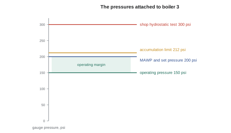
The operating margin between the normal operating pressure and the set pressure matters to the operator. A boiler run too close to its set pressure lifts its safety valves on every load swing, which wears the seats and wastes steam. A common rule in plant practice is to keep the operating pressure at least about 10 in 100 below the set pressure; Cantwell's 25 in 100 is generous, because the plant was designed for a higher pressure than the district heating loads now need.
Design temperature
The design temperature is the metal temperature used to choose the allowable stress. It is not the steam temperature but the expected temperature of the metal, which for a heated part such as a furnace tube or superheater tube is higher than the fluid inside it. For Cantwell's saturated boilers, the drum design temperature is close to the saturation temperature at the MAWP. For the tubes, the code requires an allowance above the water temperature for the heat flowing through the wall. For a superheater, the outlet tubes in the hottest gas see the highest metal temperature in the boiler and are usually the most highly alloyed parts (lesson 3).
The design temperature matters because allowable stress falls as temperature rises. For carbon steel the fall is gentle up to about 650 °F, then steeper as creep begins. A part designed for one temperature and run hotter is no longer protected by its design margin, even if the pressure is unchanged.
Allowable stress and joint efficiency
The allowable stress S for a material at the design temperature comes from Section II Part D, as lesson 1 explained, with the design margin built in. Two other factors reduce what the designer may count on:
- Weld joint efficiency E reflects how thoroughly a welded seam has been examined. A butt weld that is fully radiographed may be given an efficiency of 1.0; a Section VIII Division 1 butt weld that is spot radiographed is commonly given 0.85, and one that is not radiographed 0.70. Section I requires full examination of the main seams of drums, so E is 1.0 for those.
- Ligament efficiency, from PWR-220 and PWR-310, is the fraction of metal left between tube holes along a row. Where it is lower than the weld joint efficiency, it governs. For boiler 3's steam drum it is 0.45.
A third factor applies to seamless pipe and tube. The material specification permits the wall to be thinner than its nominal value by a manufacturing tolerance, commonly 12.5 in 100 of the nominal wall for seamless pipe. The designer must ensure that the minimum wall, not the nominal one, meets the calculated thickness.
Building up a thickness
The required thickness of a cylindrical part is built up in layers:
- The pressure thickness, from the hoop stress relation with S and E. For a thin cylinder with inside diameter D, the teaching form is t = PD ÷ 2SE. The codes' own formulas include small correction terms, which matter for thicker walls.
- The corrosion allowance, extra metal chosen by the designer or the owner to be consumed by corrosion or erosion over the item's life. The code does not usually fix its size; it requires the designer to provide what the service needs.
- Allowances for forming and manufacturing, such as thinning when plate is formed into a head, or the mill tolerance on pipe.
- The next available size: the plate, pipe or tube actually supplied is the next standard thickness above the sum.
Worked problem
A blowdown tank shell
Cantwell's blowdown tank is a Section VIII Division 1 vessel with an inside diameter of 24 in and a design pressure of 150 psi. The shell is SA-516 Grade 70 with an allowable stress of about 20,000 psi (typical) and spot-radiographed seams (E = 0.85). The corrosion allowance is 1/8 in. Find the required thickness using the teaching form, and the pressure the 5/16 in plate actually supplied could carry once the corrosion allowance is used up.
Show solution
- Pressure thickness:
- \[t = \frac{150 \times 24}{2 \times 20{,}000 \times 0.85} = \frac{3{,}600}{34{,}000} = 0.106 \text{ in}\]
- Add the corrosion allowance:
- \[t_{required} = 0.106 + 0.125 = 0.231 \text{ in}\]
- Pressure the corroded plate (0.3125 − 0.125 = 0.1875 in) could carry:
- \[P = \frac{2 S E t}{D} = \frac{2 \times 20{,}000 \times 0.85 \times 0.1875}{24} = 266 \text{ psi}\]
Answer: Pressure alone needs about 0.11 in. The corrosion allowance doubles that, and the manufacturer used 5/16 in plate, a common practical minimum for a vessel of this size that is handled, nozzled and supported. Even fully corroded to its allowance, the shell would carry about 266 psi. The nameplate MAWP is still 150 psi, because that is the design pressure and the nozzles, flanges and relief valve were chosen for it.
Tubes: why pressure is rarely the limit
A boiler tube has a small diameter, so the hoop stress from pressure is low and the thickness that pressure alone needs is small. Tubes are made much thicker for other reasons: to give a margin for corrosion and erosion over decades; to stand the expanding, or rolling, of their ends into the drum tube holes; to resist bending and handling during erection; to survive short periods of overheating; and to provide wall for sootblower erosion and fly ash wear. Section I's tube formula includes an allowance for expanded ends for this reason.
Worked problem
A furnace tube at MAWP
Boiler 3's furnace tubes are SA-178 Grade A electric resistance welded tubes, 2.0 in outside diameter with a 0.105 in wall. Use a typical allowable stress of 10,000 psi (which for this welded tube already includes a reduction for the weld) and the teaching form with the outside diameter. Find the thickness pressure alone needs at the MAWP of 200 psi, the stress in the full wall, and the stress where a pit 0.063 in deep remains.
Show solution
- Pressure thickness:
- \[t = \frac{P D_o}{2 S} = \frac{200 \times 2.0}{2 \times 10{,}000} = 0.020 \text{ in}\]
- Hoop stress in the full 0.105 in wall:
- \[\sigma = \frac{P D_o}{2 t} = \frac{200 \times 2.0}{2 \times 0.105} = 1{,}905 \text{ psi}\]
- At the pit, 0.105 − 0.063 = 0.042 in of wall remains:
- \[\sigma = \frac{400}{2 \times 0.042} = 4{,}762 \text{ psi}\]
Answer: Pressure alone needs about 0.02 in; the tube is five times thicker. Even at the deepest pit found after the summer wet layup (PWR-220), the stress is about half the allowable value. That does not make the pit acceptable: pits are local, they keep growing while oxygen is present, they concentrate stress, and a tube that overheats loses strength fast. That is why the plan is to replace the worst floor tubes at the 2027 outage and to measure the rest by ultrasonic testing.
Drums: the ligaments govern
In a drum, the tube holes govern the thickness. PWR-220 showed that boiler 3's steam drum, 42 in inside diameter with a ligament efficiency of 0.45, needed about 0.467 in for pressure plus a corrosion allowance, and that the manufacturer supplied 9/16 in plate. The same relation can be turned round to find the pressure a drum can carry with a given thickness. This is how an inspector judges a drum that has thinned in service.
Worked problem
Pressure a thinned drum could carry
Suppose an internal inspection of boiler 3's steam drum found general thinning, leaving 0.52 in of plate. Using the teaching form with S = 20,000 psi and E = 0.45, what pressure could that plate carry, and how does it compare with the MAWP? (This is an illustration; the drum has not thinned.)
Show solution
- Rearrange the relation for pressure:
- \[P = \frac{2 S E t}{D} = \frac{2 \times 20{,}000 \times 0.45 \times 0.52}{42} = 223 \text{ psi}\]
- Compare with the MAWP of 200 psi:
- \[\frac{223}{200} = 1.11\]
Answer: The thinned plate would still carry the MAWP with some of its corrosion allowance left. The inspector would want to know how fast it was thinning, which sets the next inspection (lesson 7), and the calculation would be done to the code's own formula, by the inspector or an engineer, before any decision. A drum that could no longer carry its MAWP would be repaired or re-rated to a lower pressure, with new safety valve settings, under the jurisdiction's rules.
Heads
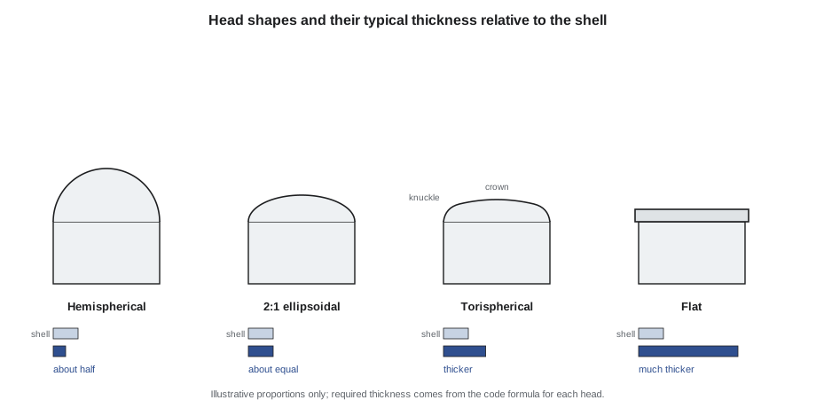
The ends of drums and vessels are closed by heads, and their shape decides how thick they must be. A sphere under pressure carries the stress pD ÷ 4t in every direction, half the hoop stress of a cylinder (PWR-310), so a hemispherical head needs only about half the thickness of the shell it closes. Other shapes are less efficient:
- Hemispherical heads are the most efficient but the deepest and most costly to form; they are used on high-pressure drums and large vessels.
- Ellipsoidal heads, most often with a 2:1 ratio of diameter to depth, need about the same thickness as the shell. They are the usual choice for vessels.
- Torispherical (flanged and dished) heads, made of a large crown radius joined to the cylinder by a small knuckle, are shallower and cheaper but thicker, because the knuckle carries high bending stress.
- Flat heads and flat covers resist pressure by bending, not membrane stress, and must be very much thicker. They are used for small openings, handhole covers and some firetube boiler tube sheets, where stays carry most of the load.
Openings for nozzles and manways remove metal from a shell or head, and the code requires that metal to be reinforced: replaced within a limited zone around the opening by extra thickness in the shell, the nozzle neck or a reinforcing pad. Boiler 3's elliptical drum manway has a reinforcing ring for this reason. A small telltale hole in a reinforcing pad lets the space under it be tested for leaks and vents any leak to show itself; it must never be plugged.
Calculating the way the exam does
Ohio's steam engineer examination includes calculation questions, and the course Okonkwo is taking covers drum, tube and head thickness and safety valve capacity. The candidate works from the formulas the course and its reference texts provide, with the symbols and units they use. Grazyna's advice was to learn the physics in the teaching form, so that any formula makes sense and its answer can be checked for size, and then to practice with the formulas the course uses.
Her checklist for any thickness question: identify the part and its code; find P, D (inside or outside, as the formula needs), S at the design temperature, and E; check the units, so that pressure and stress are in the same unit; calculate the pressure thickness; add the allowances the question gives; and compare with the thickness supplied. The answer should look sensible: a few millimeters for a tube, tens of millimeters for a large drum.
Common mistakes
MistakeUsing the operating pressure in a thickness calculation.
InsteadUse the design pressure or MAWP at the design temperature.
MistakeUsing the steam temperature as the design temperature of a heated tube.
InsteadThe design temperature is the metal temperature, higher than the fluid in a heated part.
MistakeIgnoring the ligament efficiency in a drum calculation.
InsteadWhere tube holes are present, the ligament efficiency usually governs.
MistakeTreating the corrosion allowance as spare strength.
InsteadIt is metal provided to be consumed; once it is gone, the part is at its minimum.
MistakeMixing kilopascals and megapascals, or psi and ksi, in the same formula.
InsteadPut pressure and stress in the same unit before dividing.
MistakeAssuming a tube is safe because the pressure stress is low.
InsteadPitting, overheating and erosion fail tubes long before the pressure stress alone would.
Summary and key terms
- Operating pressure, design pressure, MAWP, set pressure, accumulation and test pressure are distinct; the design pressure or MAWP at the design temperature sets the thickness.
- The design temperature is the metal temperature, which for heated parts is above the fluid temperature.
- Allowable stress comes from Section II Part D; weld joint efficiency, ligament efficiency and mill tolerance reduce what can be counted on.
- Required thickness is built from the pressure thickness, the corrosion allowance and manufacturing allowances, rounded up to an available size.
- Tubes are many times thicker than pressure requires; drums are governed by their ligaments; head thickness depends on shape.
- A measured thickness can be turned back into an allowable pressure, which is how thinned parts are judged.
- Exams and designers use the code's own formulas from the edition that applies; the teaching forms explain and check them.
- Design pressure
- The pressure used with the design temperature to calculate the thickness of each part.
- Maximum allowable working pressure
- The highest pressure at which the completed item may be operated at its design temperature.
- Accumulation
- The rise in pressure above the MAWP while the safety valves discharge at full capacity.
- Design temperature
- The metal temperature used to choose the allowable stress.
- Allowable stress
- The maximum stress permitted for a material at a temperature, with the design margin built in.
- Weld joint efficiency
- A factor that reduces the allowable stress at a weld according to the extent of its examination.
- Corrosion allowance
- Extra thickness provided to be consumed by corrosion or erosion over the item's life.
- Mill tolerance
- The amount by which pipe or tube may be thinner than its nominal wall under its specification.
- Reinforcement
- Metal added around an opening to replace the strength removed by the hole.
Practice problems
Work each problem on paper first, then reveal the answer to check.
A vessel has a design pressure of 100 psi, ID 36 in, S = 20,000 psi, E = 1.0. Find the pressure thickness by the teaching form.
Show answer
100 × 36 ÷ 40,000 = 0.090 in.
Add a 1/8 in corrosion allowance. What minimum thickness is needed?
Show answer
0.215 in.
A drum with ID 48 in, S = 20,000 psi and E = 0.5 has 3/4 in of plate. What pressure can it carry?
Show answer
2 × 20,000 × 0.5 × 0.75 ÷ 48 = 313 psi.
A boiler has an MAWP of 250 psi. What is its Section I hydrostatic test pressure?
Show answer
375 psi.
Lesson quiz · 5 questions
Score 60% or more to complete this lesson.
Create a free account to save your progress, take quizzes and earn a certificate.