
PHYS-460 · Lesson 9 of 12 · 23 min
Optical fibers: guidance, modes, attenuation and dispersion
▶ Video coming soon A video version of this lesson is on the way.
The optical fiber is the photonic device with the greatest impact on everyday life. A strand of glass about the thickness of a human hair carries light for thousands of kilometers with a loss of only a few parts in a hundred per kilometer, and a single fiber carries tens of terabits per second. Almost all international data traffic travels through fiber-optic cables under the oceans. This lesson explains how fibers guide light, how many modes they support and why single-mode fibers matter, what limits their transparency, and how dispersion spreads pulses and limits the data rate. PHYS-382 treated metallic and dielectric waveguides in general; here we specialize to the cylindrical glass guide and its engineering.
Total internal reflection and numerical aperture
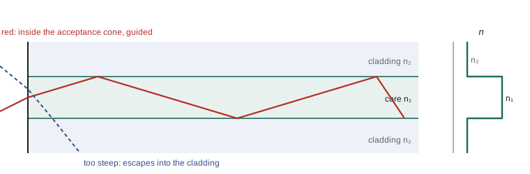
A step-index fiber has a core of refractive index \(n_1\) surrounded by a cladding of slightly lower index \(n_2\). In standard telecom fiber both are fused silica, with the core raised by a little germanium dioxide; the difference \(n_1 - n_2\) is only about 0.005. A ray inside the core striking the boundary at an angle of incidence greater than the critical angle, \(\sin\theta_c = n_2/n_1\), is totally reflected, so rays traveling close enough to the axis are trapped and zigzag along the core.
Which rays from outside can be launched into the fiber? A ray entering the flat end face from air at angle \(\theta_a\) to the axis refracts according to Snell's law, \(\sin\theta_a = n_1\sin\theta_1\), and is guided if \(\theta_1\) is small enough. Working through the geometry gives the numerical aperture,
For standard single-mode fiber the NA is about 0.12, an acceptance half-angle of about 7°; for multimode fibers it is around 0.2 to 0.3. Light entering at larger angles leaks into the cladding and is lost.
Modes and the V number
Ray optics is only an approximation when the core is a few wavelengths across. In wave optics the fiber supports a discrete set of guided modes, patterns of the field that travel along the fiber unchanged except for a phase. Their number is governed by a single dimensionless quantity, the normalized frequency or V number,
where \(a\) is the core radius. For weakly guiding fibers the modes are conveniently described as linearly polarized \(\mathrm{LP}_{lm}\) modes. The fundamental \(\mathrm{LP}_{01}\) mode, a nearly Gaussian spot, is always guided. The next mode, \(\mathrm{LP}_{11}\), is guided only when \(V > 2.405\), the first zero of the Bessel function \(J_0\). So a fiber is single-mode at wavelengths longer than the cutoff wavelength
For large \(V\), a step-index fiber supports about \(V^2/2\) modes. Standard single-mode fiber has a core about 8 µm across and a cutoff near 1.25 µm, so it is single-mode at 1.31 and 1.55 µm. Multimode fibers have cores of 50 or 62.5 µm and support hundreds of modes. They are cheaper to connect and work well with inexpensive light sources over short distances, such as within buildings and data centers. Single-mode fibers are used wherever distance or data rate matters.
Attenuation
The loss of an optical fiber is quoted in decibels per kilometer. Power after a length \(L\) is \(P(L) = P(0)\,10^{-\alpha L/10}\), where \(\alpha\) is in dB/km. Signal levels are often quoted in dBm, decibels relative to 1 mW, so a link budget becomes a sum: launched power minus fiber loss, connector loss and splice loss must exceed the receiver sensitivity with some margin.
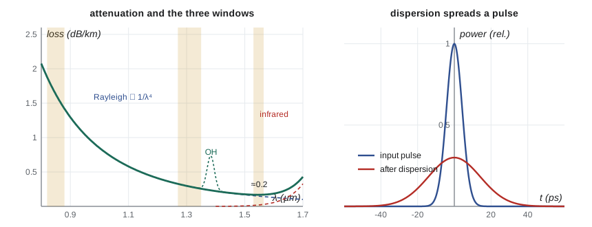
Charles Kao and George Hockham argued in 1966 that the losses of about 1,000 dB/km in the glass of the day were caused by impurities, not by the glass itself, and that losses below 20 dB/km should be possible. Corning reached that figure in 1970, and by the late 1970s losses had fallen to 0.2 dB/km at 1.55 µm, close to the fundamental limit. Three mechanisms set that limit.
Between Rayleigh scattering and infrared absorption lies a window of low loss. Telecommunications grew up in three wavelength windows: 850 nm, where early sources and silicon detectors worked; 1310 nm, where dispersion is lowest; and 1550 nm, where loss is lowest. The C band, 1530 to 1565 nm, coincides with the gain of erbium-doped fiber amplifiers.
Dispersion
A short light pulse contains a range of frequencies, and in a fiber they travel at slightly different speeds. This dispersion spreads the pulse in time, and once neighboring pulses overlap the receiver can no longer tell ones from zeros. There are three kinds.
Modal dispersion occurs in multimode fiber because different modes travel different path lengths. In the ray picture, a ray along the axis travels the length \(L\), while a ray at the critical angle travels \(L n_1/n_2\). The difference in arrival times is
tens of nanoseconds per kilometer for a step-index fiber. Graded-index multimode fibers, in which the core index falls smoothly from the axis, reduce this by a factor of a hundred or more, because rays that travel further spend more time in regions of lower index, where they move faster.
Chromatic dispersion affects every fiber, including single-mode ones. It is described by the dispersion parameter \(D\), the change in group delay per unit length per unit wavelength, usually in ps/(nm km). Material dispersion comes from the variation of the refractive index of silica with wavelength:
For silica, \(D_{mat}\) passes through zero near 1.27 µm and is about \(+22\) ps/(nm km) at 1.55 µm. Waveguide dispersion, which arises because the mode's spread into the cladding changes with wavelength, adds a negative contribution of a few ps/(nm km), so standard single-mode fiber has zero dispersion near 1.31 µm and \(D \approx 17\) ps/(nm km) at 1.55 µm. By changing the core profile, designers make dispersion-shifted fibers with zero dispersion near 1.55 µm, and dispersion-compensating fibers with large negative \(D\). In modern coherent systems, dispersion is undone digitally in the receiver.
The pulse spread from chromatic dispersion is \(\Delta t = |D|\,\Delta\lambda\,L\), where \(\Delta\lambda\) is the spectral width of the source or of the modulated signal, whichever is larger. As a rule of thumb the bit rate must satisfy \(B\,\Delta t \lesssim 1/2\). Polarization-mode dispersion, caused by tiny asymmetries that make the two polarizations travel at slightly different speeds, becomes important at the highest data rates.
Computing a fiber link
The program computes the numerical aperture, acceptance angle, V number and guided modes of a standard single-mode fiber and a step-index multimode fiber at the three telecom wavelengths; finds the modal dispersion of the multimode fiber; computes the material dispersion of fused silica from its Sellmeier equation and finds its zero; estimates the dispersion-limited bit rate for two sources; and works through the power budget of an 80 km link.
import math
c = 2.99792458e8
# step-index guide: numerical aperture, acceptance angle, V number and single-mode cutoff
cutoffs = [(0.0, 'LP01'), (2.405, 'LP11'), (3.832, 'LP21, LP02'), (5.136, 'LP31, LP12')]
for name, n1, n2, a in [('standard single-mode', 1.4494, 1.4447, 4.1e-6), ('step-index multimode', 1.4630, 1.4447, 25e-6)]:
    NA = math.sqrt(n1**2 - n2**2); theta = math.degrees(math.asin(NA))
    lam_c = 2 * math.pi * a * NA / 2.405
    print(f"{name}: core radius {a*1e6:.1f} um, NA = {NA:.3f}, acceptance half-angle = {theta:.1f} deg, LP11 cutoff {lam_c*1e9:.0f} nm")
    for lam in (850e-9, 1310e-9, 1550e-9):
        V = 2 * math.pi * a * NA / lam
        if V < 6:
            txt = ' + '.join(m for vc, m in cutoffs if V > vc)
        else:
            txt = f"about {int(V * V / 2)} modes"
        print(f"   {lam*1e9:.0f} nm: V = {V:5.2f}, guided: {txt}")
# modal dispersion in a step-index multimode guide: dt/L = n1 (n1 - n2) / (n2 c)
n1, n2 = 1.4630, 1.4447
d = n1 * (n1 - n2) / (n2 * c)
print()
print(f"step-index modal spread = {d*1e3*1e9:.1f} ns per km -> bit rate x distance about {1/(2*d)/1e6*1e-3:.1f} Mb/s km")
# material dispersion of fused silica from the Sellmeier equation
B = (0.6961663, 0.4079426, 0.8974794); C = (0.0684043**2, 0.1162414**2, 9.896161**2)   # um^2
def n(lam_um):
    l2 = lam_um**2
    return math.sqrt(1 + sum(b * l2 / (l2 - cc) for b, cc in zip(B, C)))
def D(lam_um, h=1e-3):
    """material dispersion in ps/(nm km): D = -(lam/c) d2n/dlam2"""
    d2 = (n(lam_um + h) - 2 * n(lam_um) + n(lam_um - h)) / h**2      # 1/um^2
    return -lam_um * d2 * 1e6 / c * 1e6
print()
print(f"{'lambda (um)':>12s}{'n':>9s}{'D (ps/(nm km))':>16s}")
zero = None; prev = None
for i in range(110, 171, 10):
    lam = i / 100
    Dps = D(lam)
    print(f"{lam:12.2f}{n(lam):9.5f}{Dps:16.2f}")
lo, hi = 1.1, 1.5
for _ in range(60):
    mid = (lo + hi) / 2
    if D(mid) < 0: lo = mid
    else: hi = mid
print(f"material dispersion is zero near {mid*1000:.0f} nm")
# pulse spreading and the dispersion limit at 1550 nm with D = 17 ps/(nm km)
Dsmf = 17.0
for name, dl in [('DFB laser, 0.1 nm wide (modulated)', 0.1), ('LED, 50 nm wide', 50)]:
    for L in (1, 80):
        dt = Dsmf * dl * L
        print(f"{name}: {L:3d} km -> spread {dt:9.1f} ps, rough bit-rate limit {1/(2*dt*1e-12)/1e9:8.2f} Gb/s")
# link budget at 1550 nm
P_tx, loss_km, L, conn, splice, margin = 0.0, 0.20, 80, 2 * 0.5, 16 * 0.05, 3.0
P_rx = P_tx - loss_km * L - conn - splice - margin
print()
print(f"80 km link: launched 0 dBm, received {P_rx:.1f} dBm = {10**(P_rx/10)*1e3:.1f} uW; a receiver needing -28 dBm has {P_rx+28:.1f} dB to spare")standard single-mode: core radius 4.1 um, NA = 0.117, acceptance half-angle = 6.7 deg, LP11 cutoff 1249 nm
850 nm: V = 3.53, guided: LP01 + LP11
1310 nm: V = 2.29, guided: LP01
1550 nm: V = 1.94, guided: LP01
step-index multimode: core radius 25.0 um, NA = 0.231, acceptance half-angle = 13.3 deg, LP11 cutoff 15066 nm
850 nm: V = 42.63, guided: about 908 modes
1310 nm: V = 27.66, guided: about 382 modes
1550 nm: V = 23.38, guided: about 273 modes
step-index modal spread = 61.8 ns per km -> bit rate x distance about 8.1 Mb/s km
lambda (um) n D (ps/(nm km))
1.10 1.44920 -21.48
1.20 1.44805 -7.91
1.30 1.44692 2.65
1.40 1.44578 11.25
1.50 1.44462 18.58
1.60 1.44342 25.07
1.70 1.44217 31.01
material dispersion is zero near 1273 nm
DFB laser, 0.1 nm wide (modulated): 1 km -> spread 1.7 ps, rough bit-rate limit 294.12 Gb/s
DFB laser, 0.1 nm wide (modulated): 80 km -> spread 136.0 ps, rough bit-rate limit 3.68 Gb/s
LED, 50 nm wide: 1 km -> spread 850.0 ps, rough bit-rate limit 0.59 Gb/s
LED, 50 nm wide: 80 km -> spread 68000.0 ps, rough bit-rate limit 0.01 Gb/s
80 km link: launched 0 dBm, received -20.8 dBm = 8.3 uW; a receiver needing -28 dBm has 7.2 dB to spareThe single-mode fiber, with a 4.1 µm core radius and NA 0.117, has its \(\mathrm{LP}_{11}\) cutoff at 1249 nm. At 1310 and 1550 nm it guides only the fundamental mode; at 850 nm it also guides \(\mathrm{LP}_{11}\), which is why 850 nm systems use multimode fiber. The step-index multimode fiber supports several hundred modes, and its modal spread of 62 ns per kilometer limits it to about 8 Mb/s over a kilometer, which is why multimode links use graded-index fiber.
The Sellmeier calculation shows the material dispersion of silica rising from about \(-21\) to \(+31\) ps/(nm km) across the range, through zero near 1273 nm. With the waveguide contribution added, standard fiber has \(D \approx 17\) ps/(nm km) at 1550 nm. A source of 0.1 nm spectral width suffers only 1.7 ps of spreading per kilometer but 136 ps over 80 km, enough to limit an uncompensated link to a few gigabits per second. A 50 nm wide LED spreads by nearly a nanosecond per kilometer and is useful only for short, slow links.
The 80 km link loses 16 dB in the fiber, 1 dB in two connectors and 0.8 dB in sixteen splices, and keeps a 3 dB margin; 0 dBm launched arrives as \(-20.8\) dBm, about 8 µW, leaving 7 dB to spare for a receiver that needs \(-28\) dBm. Long-haul systems place erbium-doped fiber amplifiers every 50 to 100 km to restore the signal optically. Invented in 1987 by groups at the University of Southampton and at Bell Labs, these amplifiers boost all the wavelength channels in the C band at once without converting them to electrical signals, and they made wavelength-division multiplexing, the subject of lesson 12, practical.
Worked problem
Is the fiber single-mode?
A fiber has a core radius of 3.0 µm, \(n_1 = 1.455\) and \(n_2 = 1.450\). Is it single-mode at 850 nm?
Show solution
- \(\mathrm{NA} = \sqrt{1.455^2 - 1.450^2} = \sqrt{0.01453} = 0.1205\).
- \(V = 2\pi \times 3.0 \times 10^{-6} \times 0.1205/850 \times 10^{-9} = 2.67\).
- \(V > 2.405\), so \(\mathrm{LP}_{11}\) is also guided.
Answer: No: it supports two mode groups at 850 nm. Its cutoff wavelength is \(2\pi \times 3.0 \times 0.1205/2.405 = 0.944\) µm, so it is single-mode above 944 nm.
Worked problem
Power after a long span
A transmitter launches 3 dBm into 120 km of fiber with loss 0.22 dB/km. What power arrives, in dBm and in microwatts?
Show solution
- Loss: \(0.22 \times 120 = 26.4\) dB.
- Received: \(3 - 26.4 = -23.4\) dBm.
- \(10^{-2.34}\) mW \(= 4.6 \times 10^{-3}\) mW \(= 4.6\) µW.
Answer: \(-23.4\) dBm, or about 4.6 µW: 1/437 of the launched 2.0 mW.
Common mistakes
MistakeCalling a fiber single-mode at every wavelength.
InsteadIt is single-mode only above its cutoff wavelength, where \(V < 2.405\).
MistakeAdding losses as fractions instead of decibels.
InsteadLosses in dB add; fractional transmissions multiply.
MistakeAssuming zero dispersion means no pulse spreading at all.
InsteadHigher-order dispersion and polarization-mode dispersion remain.
MistakeUsing material dispersion alone for single-mode fiber.
InsteadWaveguide dispersion shifts the zero from about 1.27 µm to about 1.31 µm.
MistakeThinking the lowest-loss wavelength is also the lowest-dispersion wavelength in standard fiber.
InsteadLoss is lowest near 1.55 µm, dispersion near 1.31 µm.
Summary and key terms
- Fibers guide by total internal reflection; \(\mathrm{NA} = \sqrt{n_1^2 - n_2^2}\) sets the acceptance angle.
- \(V = 2\pi a\,\mathrm{NA}/\lambda\); single-mode operation requires \(V < 2.405\); large-\(V\) fibers carry about \(V^2/2\) modes.
- Loss is set by Rayleigh scattering, infrared absorption and impurities; the minimum is about 0.2 dB/km near 1.55 µm.
- Modal dispersion limits step-index multimode fiber; chromatic dispersion \(D\) is about 17 ps/(nm km) at 1.55 µm in standard fiber.
- Link budgets add losses in dB; erbium amplifiers restore signals every 50 to 100 km.
- Numerical aperture
- \(\sqrt{n_1^2 - n_2^2}\), the sine of the largest acceptance angle.
- V number
- The normalized frequency \(2\pi a\,\mathrm{NA}/\lambda\) that sets the number of modes.
- Cutoff wavelength
- The wavelength above which a fiber is single-mode.
- Chromatic dispersion
- Pulse spreading caused by the wavelength dependence of the group velocity.
- dBm
- Power in decibels relative to 1 mW.
Practice problems
Work each problem on paper first, then reveal the answer to check.
Find the NA for \(n_1 = 1.48\), \(n_2 = 1.46\).
Show answer
\(\sqrt{2.1904 - 2.1316} = \sqrt{0.0588} = 0.242\).
How many modes does a fiber with \(V = 30\) support?
Show answer
About \(V^2/2 = 450\).
A link has 25 dB of loss. What fraction of the power arrives?
Show answer
\(10^{-2.5} = 3.2 \times 10^{-3}\).
Find the pulse spread for \(D = 17\) ps/(nm km), \(\Delta\lambda = 0.2\) nm, over 50 km.
Show answer
\(17 \times 0.2 \times 50 = 170\) ps.
Why does Rayleigh scattering favor long wavelengths for fibers?
Show answer
It scales as \(1/\lambda^4\), so doubling the wavelength cuts it sixteenfold.
Lesson quiz · 5 questions
Score 60% or more to complete this lesson.
Create a free account to save your progress, take quizzes and earn a certificate.