
PET-460 · Lesson 6 of 12 · 18 min
Storage site selection and characterization
Farid spread three maps across the meeting table: structure, well density and faults. “Every basin has a formation that can take CO₂,” he said. “The question is whether we can prove it will stay, to a regulator and to the people who live above it, at a cost the hub can carry. That is what site selection is: finding the place where the proof is cheapest.” He had already screened the basin under the Texas Gulf Coast and narrowed the choice to three candidates. Ethan's job was to make the ranking explicit and to plan the work that would turn the best candidate from a prospect into a characterized site.
Where CO₂ can be stored
Three kinds of geological storage are used at scale. Deep saline formations, porous rocks filled with brine too salty for any use, have by far the largest capacity: estimates for North America run to thousands of billions of metric tons. They are the target of Sleipner, Quest and most proposed hubs, but because they hold no hydrocarbons they are usually poorly characterized at first. Depleted oil and gas fields have proven seals, since they held hydrocarbons for millions of years, and abundant data, but limited capacity, reduced pressure that complicates injection, and many old wells. Enhanced oil recovery fields store CO₂ as part of producing oil, and have the longest operating record. Smaller options include mineralization in basalt and ultramafic rock, demonstrated in Iceland, where CO₂ dissolved in water turns to carbonate minerals within about two years, and unmineable coal seams, which adsorb CO₂, though low permeability has limited them.
Screening criteria
The first criteria are geological. The formation must be deep enough for CO₂ to be dense, below about 2,600 ft, but not so deep that drilling is costly and porosity poor. It needs enough thickness, porosity and permeability for capacity and injectivity. Above it there must be a regionally continuous seal, a shale, mudstone, evaporite or tight carbonate with low permeability and high capillary entry pressure, ideally with secondary seals higher up. Faults that cross the seal must be understood, and the area should have low natural seismicity and a stress state that will not be disturbed into slipping faults. Then come the man-made factors: the number and condition of existing wells that penetrate the seal, conflicts with other resources such as oil, gas, potash, geothermal heat or groundwater, distance to the sources and the ability to secure the storage rights. In many mature basins, legacy wells are the deciding factor.
# Storage site screening: a weighted scorecard for three candidate areas, and the CO2 column a caprock can hold.
import math
SI = False     # True: Canadian candidates, metric; False: US candidates, US units

# criteria: (name, weight, function of the site value giving a score 0 to 5)
def band(x, pts):          # piecewise-linear score from (value, score) pairs
    for (x1, s1), (x2, s2) in zip(pts, pts[1:]):
        if x1 <= x <= x2: return s1 + (s2 - s1) * (x - x1) / (x2 - x1)
    return pts[0][1] if x < pts[0][0] else pts[-1][1]
crit = [("depth, m", 0.10, lambda d: band(d, [(700, 0), (900, 3), (1200, 5), (2500, 5), (3500, 2)])),
        ("net thickness, m", 0.15, lambda h: band(h, [(5, 0), (20, 3), (50, 5)])),
        ("porosity", 0.10, lambda p: band(p, [(0.06, 0), (0.12, 3), (0.20, 5)])),
        ("permeability, mD", 0.15, lambda k: band(math.log10(k), [(0, 0), (1.3, 2), (2.3, 5)])),
        ("seal thickness, m", 0.20, lambda t: band(t, [(10, 0), (30, 3), (100, 5)])),
        ("legacy wells per 100 km2", 0.20, lambda w: band(w, [(0, 5), (5, 4), (25, 1), (60, 0)])),
        ("distance to sources, km", 0.10, lambda x: band(x, [(20, 5), (100, 3), (300, 0)]))]
if SI:
    sites = {"A  Basal Cambrian, Heartland": [2050, 45, 0.16, 250, 60, 1.5, 25],
             "B  Leduc reef aquifer": [1650, 60, 0.10, 600, 25, 30, 60],
             "C  depleted Viking gas pool": [850, 12, 0.18, 120, 40, 55, 90]}
    names = [c[0] for c in crit]; tom = [1, 1, 1, 1, 1, 1, 1]
else:   # field units: ft, ft, fraction, mD, ft, wells per 40 mi2 (about 100 km2), miles
    sites = {"A  Frio, Matagorda Bend": [6000, 150, 0.26, 300, 400, 6, 19],
             "B  Miocene sands, state waters": [4900, 260, 0.30, 1000, 160, 2, 44],
             "C  depleted Frio gas field": [7900, 65, 0.22, 150, 400, 50, 28]}
    names = ["depth, ft", "net thickness, ft", "porosity", "permeability, mD", "seal thickness, ft", "legacy wells per 40 mi2", "distance to sources, mi"]
    tom = [0.3048, 0.3048, 1, 1, 0.3048, 1, 1.609]
for site, vals in sites.items():
    met = [v * f for v, f in zip(vals, tom)]
    scores = [f(v) for (n, w, f), v in zip(crit, met)]
    total = sum(c[1] * sc for c, sc in zip(crit, scores))
    worst = min(zip(scores, names))
    shown = ", ".join(f"{n2.split(',')[0]} {v:,g}" for n2, v in zip(names, vals))
    print(f"{site}: score {total:.2f} of 5 (weakest: {worst[1].split(',')[0]}, {worst[0]:.1f})\n   {shown}")

# capillary seal capacity: convert a mercury-air entry pressure to CO2-brine, then to a column height
def column(pc_hg, rho_w, rho_c, ift=30e-3, theta=20.0):
    pc = pc_hg * ift * math.cos(math.radians(theta)) / (0.485 * abs(math.cos(math.radians(140))))
    return pc, pc / ((rho_w - rho_c) * 9.81)
rho_w, rho_c = (1180.0, 704.0) if SI else (1065.0, 573.0)
print("\nCaprock capillary seal capacity")
for lab, pchg in (("tight shale sample", 20e6), ("siltier shale sample", 4e6), ("sandy seal interval", 0.6e6)):
    pc, h = column(pchg, rho_w, rho_c)
    if SI: print(f"  {lab:22s} Hg-air entry {pchg / 1e6:5.1f} MPa -> CO2-brine {pc / 1e3:6.0f} kPa -> column {h:6.0f} m")
    else:  print(f"  {lab:22s} Hg-air entry {pchg / 6894.8:6,.0f} psi -> CO2-brine {pc / 6894.8:5.0f} psi -> column {h * 3.281:6,.0f} ft")
print(f"The hub's maximum plume thickness under the seal is about {'45 m' if SI else '150 ft'}: the weakest sample still matters only if it is continuous.")A Frio, Matagorda Bend: score 4.70 of 5 (weakest: legacy wells per 40 mi2, 3.9) depth 6,000, net thickness 150, porosity 0.26, permeability 300, seal thickness 400, legacy wells per 40 mi2 6, distance to sources 19 B Miocene sands, state waters: score 4.50 of 5 (weakest: seal thickness, 3.5) depth 4,900, net thickness 260, porosity 0.3, permeability 1,000, seal thickness 160, legacy wells per 40 mi2 2, distance to sources 44 C depleted Frio gas field: score 3.63 of 5 (weakest: legacy wells per 40 mi2, 0.3) depth 7,900, net thickness 65, porosity 0.22, permeability 150, seal thickness 400, legacy wells per 40 mi2 50, distance to sources 28 Caprock capillary seal capacity tight shale sample Hg-air entry 2,901 psi -> CO2-brine 220 psi -> column 1,032 ft siltier shale sample Hg-air entry 580 psi -> CO2-brine 44 psi -> column 206 ft sandy seal interval Hg-air entry 87 psi -> CO2-brine 7 psi -> column 31 ft The hub's maximum plume thickness under the seal is about 150 ft: the weakest sample still matters only if it is continuous.
The scorecard put the Frio Formation beneath Matagorda Bend first by a clear margin. The Frio sands at about 6,000 ft are thick, porous and permeable, the target of the Frio brine pilot tests of 2004 and 2006, and capped by the Anahuac shale, a regional seal several hundred feet thick. Their weakness is the density of old oil and gas wells in parts of the coast; the hub area was chosen where the Frio is below most production. The state-waters Miocene sands scored nearly as well and remain a second phase option, while the depleted Frio gas field scored lower because of its many wells, despite its proven seal. Farid's comment was that a scorecard ranks candidates; it does not prove one, and that the weights were judgments the team should be ready to defend.
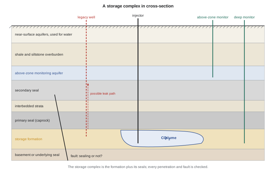
The seal and its capacity
A seal holds CO₂ by capillary pressure. Brine wets the small pores of a shale, and CO₂ can enter them only when the pressure difference across the CO₂-brine interface exceeds the capillary entry pressure, which is inversely proportional to the pore throat radius. Laboratory mercury injection capillary pressure (MICP) tests on seal core give the entry pressure for mercury and air, which is converted to CO₂ and brine using interfacial tension and contact angle:
With γ about 0.485 N/m and θ = 140° for mercury, and γ about 0.025 to 0.035 N/m and θ = 0 to 40° for CO₂ and brine, the conversion factor is about 0.07 to 0.09. The maximum CO₂ column the seal can hold before CO₂ enters it is then:
A tight shale with a mercury entry pressure of 2,900 psi holds a column of over 1,000 ft, far more than any plume. A silty seal or a sandy interval holds much less, and a seal is only as good as its weakest continuous layer, so sampling along the seal and mapping its facies matter more than one excellent core. Interfacial tension and wettability are uncertain at reservoir conditions; some shales are less water-wet to CO₂ than to hydrocarbons, so Mei planned measurements on Anahuac shale core with CO₂ and brine at reservoir conditions.
Worked problem
Column height from a seal sample
MICP gives a mercury-air entry pressure of 870 psi for a caprock sample. Use γ = 0.030 N/m and θ = 20° for CO₂-brine, and γ = 0.485 N/m and θ = 140° for mercury-air. Brine density is 1,065 kg/m³ and CO₂ density 573 kg/m³. Find the column height the seal can hold.
Show solution
- Conversion factor = (0.030 × cos 20°) / (0.485 × |cos 140°|) = 0.0282 / 0.3715 = 0.0759.
- CO₂-brine entry pressure = 870 psi × 0.0759 = 66 psi (455 kPa).
- Density difference = 1,065 − 573 = 492 kg/m³.
- h_max = 455,000 / (492 × 9.81) = 94 m, or 310 ft.
Answer: The seal could hold a CO₂ column of about 310 ft, more than twice the maximum plume thickness under the seal. A capillary seal can fail in other ways, through faults, fractures or wells, which characterization must also address.
Characterization: from prospect to site
A characterization program typically takes three to five years and costs tens of millions of US dollars. Its steps follow those of an oil and gas appraisal, but with different questions.
Data review and regional geology come first: logs, cores, drill-stem tests and production data from existing wells, regional seismic, and published studies. The aim is a regional model of the storage formation, its seals and the aquifers above, from which the area that a plume and the associated pressure might affect, the area of review, can be estimated.
New seismic follows. A 3D survey over the expected plume area maps faults, the structure of the seal and the internal architecture of the formation, and becomes the baseline for monitoring repeat surveys in Lesson 10. On the Gulf Coast, growth faults and salt domes make fault mapping the critical seismic task.
A stratigraphic test well, drilled through the whole storage complex, provides cores of the formation and the seals, a full log suite, formation pressure measurements, brine samples and stress tests. A minifrac or extended leak-off test in the seal measures the minimum horizontal stress, the basis of the fracture pressure limit. An injection test with water, and sometimes CO₂, measures injectivity, permeability and boundaries with the well testing methods of earlier courses; a step-rate test finds the pressure at which the rock starts to fracture.
Laboratory work runs alongside: porosity and permeability, relative permeability and residual saturation for CO₂ and brine, capillary pressure, rock mechanics of the seal and formation, brine chemistry and its reaction with CO₂ and the minerals, and seal capillary entry pressure. These feed a static geological model and a dynamic simulation model, which predict the plume, the pressure and their uncertainty, the basis for the permit application.
| Question | Main data | Typical result for the decision |
|---|---|---|
| Is there enough pore volume? | seismic, logs, cores | capacity range, P10 to P90 |
| Can wells inject the planned rate? | injection test, core permeability | injectivity per well, number of wells |
| Will the seal hold? | seal core, MICP, logs, regional mapping | column height, continuity |
| Will injection slip faults or fracture the seal? | stress tests, rock mechanics, fault mapping | maximum injection pressure |
| What could leak, and where? | well records, field inspection | legacy well risk and remediation plan |
| How far will pressure and CO₂ spread? | simulation, boundaries | area of review and monitoring plan |
Legacy wells
Every well that penetrates the seal is a potential leak path, through deteriorated cement, corroded casing or an inadequate plug. Texas has more than a million wells drilled over a century, many before modern plugging rules, and the Gulf Coast's shallow Miocene and Frio sections are heavily drilled. Within the Matagorda Bend area, about forty wells penetrate the Anahuac shale. For each one, the team gathers drilling, completion and abandonment records, checks the plugs against current rules, and decides whether it needs re-entry and remediation. Wells within the area that the plume or significant pressure will reach must be shown to be adequately plugged before injection starts. Locating old wells whose records are lost is a real problem; magnetic surveys and old maps help.
Induced seismicity and stress
Injecting fluid raises pore pressure, which reduces the effective normal stress on faults and can trigger slip if a fault is already close to failure. Wastewater disposal in Oklahoma in the 2010s caused a large increase in felt earthquakes, and that experience shapes how regulators view large-volume CO₂ injection. The characterization program maps faults, measures the stress magnitudes and orientation, estimates how close each fault is to slip, and sets the maximum injection pressure with a margin. A microseismic array, part of the monitoring plan, records small events so that operations can be adjusted long before a felt earthquake. Most storage projects, including Quest, have recorded only very small events.
Common mistakes
MistakeChoosing a site on capacity alone.
InsteadWeigh seal quality, legacy wells, faults and pressure limits; the proof of containment usually decides the site.
MistakeRelying on one excellent seal core.
InsteadA seal is only as good as its weakest continuous interval; sample and map its facies.
MistakeTreating old wells as safe because they are plugged.
InsteadCheck every penetration's records and plugs against current rules; remediate wells within the area of review.
MistakeSetting the injection pressure limit from a regional fracture gradient.
InsteadMeasure the minimum stress in the seal and check fault stability at the site.
Summary and key terms
- Storage options are deep saline formations, depleted oil and gas fields, EOR fields and, at smaller scale, basalt and coal.
- Screening considers depth, thickness, porosity, permeability, seals, faults, seismicity, legacy wells, resource conflicts and distance.
- Seal capacity is set by capillary entry pressure; MICP results are converted to CO₂-brine and then to column height.
- Characterization adds 3D seismic, a stratigraphic test well with cores, stress and injection tests, laboratory work and models.
- Legacy wells and fault stability are the most common reasons sites are rejected or limited.
- Saline formation
- A porous rock filled with brine unsuitable for other uses, the largest storage resource.
- Storage complex
- The storage formation together with its seals and any secondary containment.
- Capillary entry pressure
- The pressure difference needed for CO₂ to enter the pores of a water-wet seal.
- Area of review
- The region around a storage project that the plume or significant pressure increase may affect.
- Legacy well
- An existing well, often old, that penetrates the storage complex.
- Stratigraphic test well
- A well drilled to collect cores, logs and test data through the storage complex.
Practice problems
Work each problem on paper first, then reveal the answer to check.
A seal sample has a CO₂-brine entry pressure of 44 psi. With a density difference of 30 lb/ft³, what column can it hold?
Show answer
44 / (30 / 144) = 211 ft.
Why are depleted gas fields attractive and why are they often not chosen?
Show answer
Proven seals and data; but limited capacity, depleted pressure and many old wells.
What test measures the stress that sets the fracture pressure limit?
Show answer
A minifrac or extended leak-off test in the seal.
Name two kinds of data a stratigraphic test well provides.
Show answer
Cores of formation and seal, logs, pressures, brine samples, stress and injection tests.
Lesson quiz · 5 questions
Score 60% or more to complete this lesson.
Create a free account to save your progress, take quizzes and earn a certificate.