
PET-340 · Lesson 8 of 12 · 18 min
Artificial lift selection and sucker-rod pumping
Nodal analysis gave the 4-22H about six months of natural flow, and Marisol has asked Ethan to plan its lift for its whole life. 'Gas lift will probably carry it through the high-rate years,' she says, 'but almost every Bakken well ends on a rod pump. Do the selection properly, then design the rod pump it will need in its third year, so we know the pad has room for the unit.' Ethan starts with a screening of the methods available, then works through the sucker-rod pump.
This lesson covers the main artificial lift methods and how to choose among them, then the sucker-rod pumping system in detail: its surface unit, rod string and downhole pump, the basic calculations of displacement, loads and torque, the use of dynamometer cards for diagnosis, and the common problems of gas interference, fluid pound and rod failures.
The artificial lift methods
Every artificial lift method does one of two things: it adds energy to the fluid with a pump, or it reduces the density of the fluid column with injected gas. The main methods are the following.
Sucker-rod pumping (beam pumping) uses a reciprocating plunger pump at the bottom of the tubing, driven by a string of steel or fiberglass rods from a surface pumping unit. It is the most widely used method in the world for onshore oil wells, simple to operate and easy to service, and it can pump a well down to a very low bottomhole pressure.
Gas lift injects high-pressure gas into the tubing through valves, lightening the column. It handles high rates, sand and high gas-liquid ratios well, has few moving parts downhole, and suits deviated wells, but it needs a supply of compressed gas and cannot draw the bottomhole pressure down as far as a pump.
Electric submersible pumps (ESPs) are multistage centrifugal pumps driven by a downhole electric motor. They lift the highest volumes of any method, but they are expensive, sensitive to gas and solids, and need a workover rig to replace.
Progressing cavity pumps (PCPs) use a helical rotor turning inside an elastomer stator. They handle viscous oil and sand well and are efficient at low to moderate rates and depths, but the elastomer limits temperature and depth.
Plunger lift uses the well's own gas to drive a free plunger that carries slugs of liquid up the tubing. It is cheap and needs no outside energy, and it suits gas wells and high-GLR oil wells with low liquid rates.
Hydraulic pumps (jet and piston) use high-pressure power fluid pumped from surface to drive a downhole pump. Jet pumps have no moving parts and handle solids well, but they are less efficient.
Choosing a method
Lift selection weighs the well's conditions against each method's capabilities and costs: the rate range over the well's life, depth, the gas-liquid ratio, solids, fluid viscosity, temperature, well deviation, the power and gas available at the site, the operator's experience and service base, and the capital and operating costs. Most companies use a screening matrix to narrow the choice, followed by a detailed design and an economic comparison of the best two or three options.
# Artificial lift screening and a first sucker-rod pumping design (displacement, Mills loads, gearbox torque)
SI = False
# screening: score each method 0-3 against this well's conditions (a qualitative teaching matrix)
methods = ["rod pump", "gas lift", "ESP", "PCP", "plunger"]
if SI:   # 04-22 Cardium after natural flow ends: 1,560 m TVD, 40 m3/d gross, GLR ~85 m3/m3, some sand
    cond = {"depth": [3, 3, 3, 2, 3], "rate range": [3, 2, 1, 2, 1], "gas handling": [2, 3, 1, 1, 3],
            "solids": [2, 3, 1, 3, 2], "deviated wellbore": [2, 3, 2, 1, 2], "power and cost": [3, 1, 1, 3, 3]}
    S, N, D, ev, depth_ft, net_ft, sg, wr = 100.0, 9.0, 1.75, 0.80, 4757.0, 4265.0, 0.89, 1.9
    show_q = lambda b: f"{b / 6.2898:,.1f} m3/d"; show_l = lambda lb: f"{lb * 4.448 / 1000:,.1f} kN"
    show_t = lambda inlb: f"{inlb * 0.1130 / 1000:,.1f} kN·m"; need = 40.0 * 6.2898
else:    # 4-22H Bakken in late life: pump at 9,500 ft, 300 bbl/d gross, high GLR, tight pad
    cond = {"depth": [2, 2, 3, 1, 2], "rate range": [3, 1, 1, 1, 1], "gas handling": [2, 3, 1, 1, 3],
            "solids": [2, 3, 1, 3, 2], "deviated wellbore": [2, 3, 2, 1, 2], "power and cost": [3, 1, 1, 3, 3]}
    S, N, D, ev, depth_ft, net_ft, sg, wr = 192.0, 7.5, 1.50, 0.80, 9500.0, 8000.0, 0.93, 2.2
    show_q = lambda b: f"{b:,.0f} bbl/d"; show_l = lambda lb: f"{lb:,.0f} lbf"; show_t = lambda inlb: f"{inlb / 1000:,.0f} thousand in-lbf"
    need = 300.0
tot = [sum(v[i] for v in cond.values()) for i in range(len(methods))]
print("screening score (higher is better):", ", ".join(f"{m} {t}" for m, t in sorted(zip(methods, tot), key=lambda x: -x[1])))
PD = 0.1166 * S * N * D * D                  # pump displacement, bbl/d (S in, D in)
q = PD * ev
Ap = 3.1416 * D * D / 4
Wf = 0.433 * sg * net_ft * Ap                # fluid load on the plunger, lbf
Wr = wr * depth_ft                           # rod weight in air, lbf
a = S * N * N / 70500                        # Mills acceleration factor
PPRL = Wf + Wr * (1 + a); MPRL = Wr * (1 - a - 0.127 * sg)
torque = (PPRL - MPRL) * S / 4               # rough peak gearbox torque, in-lbf
hhp = q * net_ft * sg * 7.36e-6              # hydraulic horsepower
print(f"pump: {D} in plunger, {S:.0f} in stroke, {N} strokes/min -> displacement {show_q(PD)}, about {show_q(q)} at {ev:.0%} efficiency (need {show_q(need)})")
print(f"peak polished rod load {show_l(PPRL)}, minimum {show_l(MPRL)}; acceleration factor {a:.3f}")
print(f"approximate peak gearbox torque {show_t(torque)}; hydraulic power {hhp:.1f} hp ({hhp * 0.7457:.1f} kW)")
print(f"stress check needs the rod taper design (API RP 11L or a wave-equation program); ratio MPRL/PPRL = {MPRL / PPRL:.2f}")screening score (higher is better): rod pump 14, gas lift 13, plunger 13, PCP 10, ESP 9 pump: 1.5 in plunger, 192 in stroke, 7.5 strokes/min -> displacement 378 bbl/d, about 302 bbl/d at 80% efficiency (need 300 bbl/d) peak polished rod load 29,795 lbf, minimum 15,230 lbf; acceleration factor 0.153 approximate peak gearbox torque 699 thousand in-lbf; hydraulic power 16.5 hp (12.3 kW) stress check needs the rod taper design (API RP 11L or a wave-equation program); ratio MPRL/PPRL = 0.51
The screening for the 4-22H in its third year, at about 300 bbl/d of gross liquid, gives the rod pump 14 points, ahead of gas lift and plunger lift at 13. Gas lift becomes less efficient at low rates and low reservoir pressure, when the injection gas has to lift a heavy column with little help from the formation gas, and its compression costs continue. The rod pump can pull the well down further and costs less to run, provided the pump is set above the lateral with a good gas separator. Marisol notes that this is why most Bakken wells end their lives on rods.
The sucker-rod pumping system
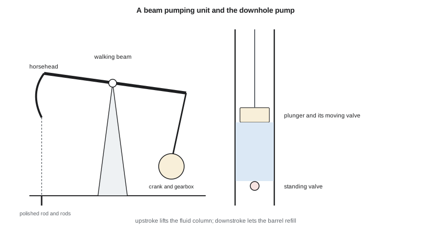
A sucker-rod system has three parts. At surface, a pumping unit converts the rotation of a motor into reciprocating motion. In the conventional beam unit, a motor drives a gearbox, the gearbox turns a crank, and the crank rocks a walking beam on a central bearing. The horsehead at the end of the beam carries the polished rod, which passes through a stuffing box at the wellhead. Counterweights on the crank balance the rod and fluid loads so that the gearbox torque is as even as possible.
The rod string connects the polished rod to the downhole pump. Rods are made in standard lengths and diameters, often in a tapered string with larger rods at the top, where loads are highest, and smaller rods at the bottom. Steel rods are standard; fiberglass rods are lighter and allow deeper pumping or more stroke at the pump, but they cannot carry compression. Sinker bars at the bottom keep the lower rods in tension.
The downhole pump is a plunger moving in a barrel, with two ball-and-seat check valves. The standing valve at the bottom of the barrel lets fluid in; the traveling valve in the plunger lets fluid through on the downstroke. On the upstroke, the traveling valve closes, the plunger lifts the fluid column above it, and fluid from the well enters the barrel through the standing valve. On the downstroke, the standing valve closes, the traveling valve opens, and the plunger moves down through the fluid in the barrel. Rod pumps are run on the rods and can be pulled without moving the tubing; tubing pumps have the barrel built into the tubing and offer a larger bore for higher rates.
Displacement and loads
The theoretical pump displacement is the volume swept by the plunger each stroke times the strokes per minute. In field units it is often written with a constant that combines the conversions.
The actual rate is lower because of gas in the pump, leakage past the plunger and the difference between the polished rod stroke and the plunger stroke, which is shortened by rod stretch and lengthened by overtravel. A volumetric efficiency of 70 to 85 percent is typical of a well-designed system.
The loads on the polished rod set the size of the pumping unit and the rods. On the upstroke, the rods carry their own weight, the weight of the fluid above the plunger and dynamic loads from acceleration. On the downstroke, they carry only their buoyant weight, reduced by dynamics. The simple Mills method estimates the peak and minimum loads using an acceleration factor that depends on stroke length and speed.
The peak gearbox torque is approximately the difference between peak and minimum loads times a quarter of the stroke, assuming good counterbalance. These simple methods were widely used for decades; they have since been replaced in design by the API RP 11L method, which uses dimensionless charts from electrical analog studies of rod dynamics, and by wave-equation programs that solve the damped wave equation for the rod string and predict the full load-position card at surface and at the pump.
Ethan's first design for the 4-22H uses a 1.5 in plunger on a 192 in stroke at 7.5 strokes per minute. The displacement is about 378 bbl/d, or about 302 bbl/d at 80 percent efficiency, enough for the 300 bbl/d of gross liquid expected in the third year. The peak polished rod load is about 29,800 lbf and the minimum about 15,200 lbf, and the peak torque is about 700,000 in-lbf, which points to a large unit, typically a long-stroke unit rated at about 912,000 in-lbf, on the pad. The hydraulic power is about 16.5 hp; the motor will be larger, because of losses in the rods, gearbox and pump.
These are first estimates. Before ordering equipment, the design must be checked with a wave-equation program, the rod taper must be selected so that the stress in each section stays within the allowable range on a modified Goodman diagram, and the counterbalance must be set so that the gearbox is not overloaded on either stroke.
Reading dynamometer cards
A dynamometer measures the load on the polished rod at each point of the stroke. Plotted against position, the measurements form a surface card. Wave-equation software converts the surface card into a downhole card, the load on the pump plunger, which has characteristic shapes that reveal how the pump is working. A full rectangular card shows a pump filling completely on each stroke. A card with a cut-off corner on the downstroke shows fluid pound, where the barrel is only partly full and the plunger strikes the fluid surface, which damages rods and pumps. A rounded corner shows gas interference, where gas in the barrel compresses before the traveling valve opens. A card that leans or narrows shows leaking valves, worn plungers or a stuck pump.
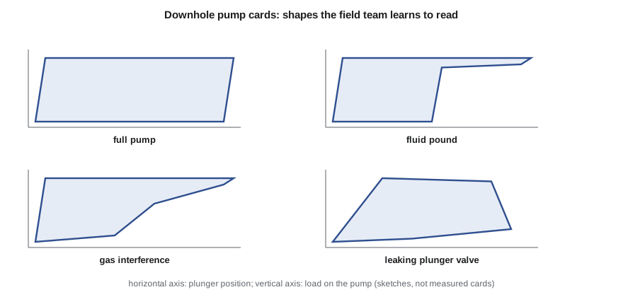
Modern wells use pump-off controllers or variable-speed drives that read the card every stroke and slow the unit or stop it when the pump begins to pound, restarting after the fluid level recovers. These controllers reduce failures, save power and keep the well producing near its potential, and their data also feed the surveillance work of lesson 12.
Common problems
Gas interference is the most common problem in high-GLR wells such as the horizontal wells of this course. Free gas entering the pump reduces its efficiency and can cause gas lock, in which the pump compresses and expands gas without opening its valves. Remedies include setting the pump below the perforations where possible, which is not possible in horizontal wells, using downhole gas separators that let gas escape up the annulus before the fluid enters the pump, and pumps with special valves or compression ratios.
Rod and tubing wear occurs where rods rub against the tubing, especially in deviated sections, and leads to holes in the tubing and parted rods. Rod guides, rotators, coated tubing and careful design of the rod path reduce it.
Rod failures come from fatigue, corrosion and overload. Corrosion inhibitors, proper make-up of couplings and staying within the Goodman diagram limits extend rod life. A field's failure frequency, the number of failures per well per year, is one of the main measures of rod-pumping performance.
Common mistakes
MistakeChoosing lift by habit rather than screening.
InsteadScreen the methods against the well's conditions over its whole life.
MistakeSizing the pump for theoretical displacement.
InsteadAllow for volumetric efficiency, typically 70 to 85 percent.
MistakeRelying on Mills estimates for final design.
InsteadCheck with API RP 11L or a wave-equation program and a Goodman diagram.
MistakePumping a horizontal well without gas separation.
InsteadUse a downhole gas separator and set the pump above the lateral.
MistakeLetting a well pound fluid.
InsteadUse a pump-off controller or variable-speed drive.
Summary and key terms
- Artificial lift adds energy with a pump or lightens the column with gas.
- Selection weighs rate, depth, GLR, solids, deviation, power and cost over the well's life.
- A rod pump system has a surface unit, a rod string and a downhole plunger pump.
- Displacement depends on plunger size, stroke and speed; actual rate is lower.
- Polished rod loads and torque size the unit; wave-equation programs refine the design.
- Dynamometer cards diagnose pump filling, gas interference and leaks.
- Sucker-rod pump
- A reciprocating plunger pump driven by rods from a surface unit.
- Polished rod
- The top rod that passes through the stuffing box and carries the string.
- Standing valve
- The fixed check valve at the bottom of the pump barrel.
- Traveling valve
- The check valve in the moving plunger.
- Dynamometer card
- A plot of rod load against position over a pump stroke.
- Fluid pound
- The plunger striking the fluid surface in a partly filled barrel.
- Pump-off controller
- A device that stops or slows the pump when the barrel stops filling.
Practice problems
Work each problem on paper first, then reveal the answer to check.
A pump has a 2.0 in plunger, a 120 in stroke and 6 strokes/min. What is its theoretical displacement?
Show answer
0.1166 × 120 × 6 × 4 = 336 bbl/d.
Why can fiberglass rods not be used at the bottom of the string?
Show answer
They cannot carry compression; sinker bars or steel rods keep the lower string in tension.
What card shape indicates fluid pound?
Show answer
A sharp cut-off on the downstroke where the plunger strikes the fluid.
Name two remedies for gas interference.
Show answer
A downhole gas separator and a pump with a higher compression ratio.
Lesson quiz · 5 questions
Score 60% or more to complete this lesson.
Create a free account to save your progress, take quizzes and earn a certificate.