
PET-340 · Lesson 10 of 12 · 21 min
Electric submersible pumps, progressing cavity pumps and plunger lift
Three other lift methods matter in Prairie Crest's operations, and Marisol wants Ethan to understand each well enough to check a vendor's design. Some Bakken operators put new wells on electric submersible pumps rather than gas lift, and the company is considering one for the 4-22H. A shallow well the company operates in another field runs a progressing cavity pump. And the 10-9 gas well from lesson 5 is about to get a plunger.
This lesson covers the electric submersible pump system and its design by total dynamic head, the progressing cavity pump and its limits, and plunger lift for gas wells and high-GLR oil wells, with a screen for when each fits.
Electric submersible pumps
An electric submersible pump (ESP) is a multistage centrifugal pump driven by an electric motor, both installed at the bottom of the tubing. Each stage consists of a rotating impeller and a stationary diffuser. The impeller adds velocity to the fluid, and the diffuser converts it to pressure. Stages are stacked by the dozen or hundred in a housing, so the pump's total head is the head per stage times the number of stages.
Below the pump, a downhole string includes an intake, often combined with a rotary or vortex gas separator; a seal section or protector, which keeps well fluid out of the motor and balances internal pressure; the motor, a three-phase induction or permanent-magnet machine filled with dielectric oil; and a sensor that measures intake pressure, temperature and vibration. Power reaches the motor through an armored power cable strapped to the tubing, from a transformer and variable-speed drive at surface.
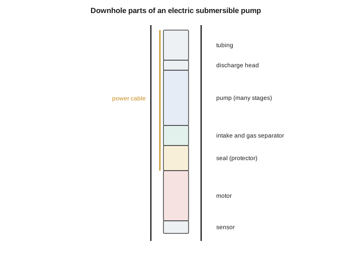
ESPs lift the largest volumes of any artificial lift method, from about 15 m³/d to more than 4,000 m³/d (about 100 to more than 25,000 bbl/d), and they are efficient at high rates. A variable-speed drive lets the operator change the pump speed and therefore its rate and head, which matters in wells whose productivity changes, such as new fractured horizontals. Their weaknesses are sensitivity to free gas, which reduces head and can cause gas lock; to sand and abrasive solids, which wear the stages; and to heat, which shortens motor and cable life. Replacing a failed ESP requires a workover rig, so run life, the average time between failures, dominates ESP economics. Run lives range from a few months in harsh wells to several years in clean, cool ones.
Designing an ESP
An ESP is designed around its total dynamic head (TDH): the head, expressed as a height of the produced fluid, that the pump must add to deliver the target rate at the chosen intake pressure. TDH has three parts: the net lift, the vertical distance from the dynamic fluid level in the annulus to the surface; the friction head in the tubing at the design rate; and the wellhead pressure expressed as a height of fluid.
The design steps are standard. First, the IPR gives the bottomhole pressure at the target rate, and from it the pump intake pressure, keeping enough pressure at the intake to limit free gas. Second, the TDH is calculated. Third, a pump model is chosen whose best efficiency point is close to the target rate, so that it runs within its recommended operating range; outside that range, thrust wear and efficiency losses shorten its life. Fourth, the number of stages is TDH divided by head per stage at the design rate. Fifth, the brake horsepower is the number of stages times the power per stage times the fluid's specific gravity, and the motor is sized above it. Finally, cable, transformer and drive are chosen to match the motor's voltage and current, allowing for voltage drop down the long cable.
# Electric submersible pump sizing (total dynamic head, stages, power), PCP speed, and a plunger-lift screen
SI = False
if SI:   # ca cases: waterflood pilot producer (ESP), heavy-oil style PCP check, Birch Coulee gas well (plunger)
    q, pump_ft, pip, pwh, sg, fric_ft = 120 * 6.2898, 1450 / 0.3048, 2000 * 0.145038, 700 * 0.145038, 1.03, 90.0
    head_stage, hp_stage = 21.0, 0.25           # small 400-series pump near its best efficiency point (illustrative)
    pcp_disp, pcp_eff, pcp_need = 0.40 * 6.2898, 0.70, 60 * 6.2898   # bbl/d per rpm
    gas_depth, glr, pc, pline = 2100 / 0.3048, 2400 * 5.6146 / 1000, 1500 * 0.145038, 900 * 0.145038
    sq = lambda b: f"{b / 6.2898:,.0f} m3/d"; sh = lambda f: f"{f * 0.3048:,.0f} m"; sp = lambda p: f"{p / 0.145038:,.0f} kPa"
    pk = lambda h: f"{h * 0.7457:,.0f} kW"
else:    # us cases: 4-22H early life (ESP option), PCP check for a shallow well, Birch Coulee gas well (plunger)
    q, pump_ft, pip, pwh, sg, fric_ft = 1800.0, 9600.0, 800.0, 200.0, 1.02, 250.0
    head_stage, hp_stage = 44.0, 0.55
    pcp_disp, pcp_eff, pcp_need = 2.5, 0.70, 380.0
    gas_depth, glr, pc, pline = 6900.0, 84.0, 220.0, 130.0
    sq = lambda b: f"{b:,.0f} bbl/d"; sh = lambda f: f"{f:,.0f} ft"; sp = lambda p: f"{p:,.0f} psi"; pk = lambda h: f"{h:,.0f} hp"
grad = 0.433 * sg                                     # psi/ft
fluid_level_above_pump = pip / grad
net_lift = pump_ft - fluid_level_above_pump
pwh_head = pwh / grad
tdh = net_lift + fric_ft + pwh_head
stages = int(tdh / head_stage) + 1
bhp = stages * hp_stage * sg
print(f"ESP: target {sq(q)}; pump at {sh(pump_ft)} with intake pressure {sp(pip)}")
print(f"   net lift {sh(net_lift)} + tubing friction {sh(fric_ft)} + wellhead pressure head {sh(pwh_head)} = TDH {sh(tdh)}")
print(f"   about {stages} stages at {sh(head_stage)} per stage; brake power about {pk(bhp)} -> choose the next motor size up")
rpm = pcp_need / (pcp_disp * pcp_eff)
print(f"PCP: {sq(pcp_need)} needs about {rpm:.0f} rpm at {pcp_eff:.0%} volumetric efficiency (keep below about 300-400 rpm for long stator life)")
need_glr = 400 * gas_depth / 1000 / 1000           # Mscf/bbl: rule of thumb 400 scf/bbl per 1,000 ft
gl = (lambda r: f"{r * 1000 / 5.6146:,.0f} m3/m3") if SI else (lambda r: f"{r * 1000:,.0f} scf/bbl")
print(f"plunger lift screen: well GLR {gl(glr)} vs rule-of-thumb need {gl(need_glr)} -> {'enough gas' if glr > need_glr else 'not enough gas'}")
print(f" casing pressure {sp(pc)} vs 1.5 x line pressure {sp(1.5 * pline)} -> {'can lift the plunger and slug' if pc >= 1.5 * pline else 'marginal: lower line pressure or add a compressor'}")ESP: target 1,800 bbl/d; pump at 9,600 ft with intake pressure 800 psi net lift 7,789 ft + tubing friction 250 ft + wellhead pressure head 453 ft = TDH 8,491 ft about 193 stages at 44 ft per stage; brake power about 108 hp -> choose the next motor size up PCP: 380 bbl/d needs about 217 rpm at 70% volumetric efficiency (keep below about 300-400 rpm for long stator life) plunger lift screen: well GLR 84,000 scf/bbl vs rule-of-thumb need 2,760 scf/bbl -> enough gas casing pressure 220 psi vs 1.5 x line pressure 195 psi -> can lift the plunger and slug
For the ESP option on the 4-22H, with a target of 1,800 bbl/d of gross liquid from a pump set at 9,600 ft with an intake pressure of 800 psi, the TDH is about 8,490 ft, mostly net lift. A pump that develops about 44 ft per stage near this rate needs about 193 stages and about 108 hp of brake power, so the vendor would propose the next larger motor. Ethan notes the challenge the transient IPR of lesson 3 creates: the well's productivity will fall by more than half in its first year, so a pump sized for 1,800 bbl/d will soon run far to the left of its best efficiency point unless its speed is reduced or it is replaced with a smaller one.
Progressing cavity pumps
A progressing cavity pump (PCP) consists of a single helical steel rotor turning inside a double-helical elastomer stator. As the rotor turns, a series of sealed cavities moves from the intake to the discharge, carrying fluid with a smooth, non-pulsing flow. The pump's displacement is fixed per revolution, so the rate is proportional to speed, less slippage, which rises with pressure and with fluid of low viscosity.
Most PCPs are driven from surface through a rotating rod string by an electric motor and drivehead at the wellhead; some use a downhole electric motor like an ESP. PCPs excel with viscous oil and sandy fluids, which they move without the valve problems of rod pumps or the abrasion of ESP stages, and they are energy efficient. That is why they dominate the cold heavy-oil production with sand in the Lloydminster area of Alberta and Saskatchewan. Their limits come from the elastomer: it swells or hardens in contact with aromatic crudes, CO₂ and some chemicals, it degrades above about 120 to 150 °C, and its fit with the rotor limits the pressure rise per stage, which limits depth to a few thousand meters or less. Rod wear in deviated wells is a further problem, because the rods rotate continuously.
PCP design starts with the required rate and the head. The engineer chooses a pump model with enough displacement per revolution and enough pressure rating, allowing for slippage, and sets the speed. Speeds in the range of 100 to 300 or 400 rpm are typical; higher speeds raise rod wear and stator fatigue.
For the company's shallow well producing 380 bbl/d, a pump with a displacement of 2.5 bbl/d per rpm needs about 217 rpm at 70 percent volumetric efficiency, within the usual range.
Plunger lift
Plunger lift uses a free-traveling plunger, a short cylinder with a seal against the tubing wall, to lift liquid with the well's own gas. A cycle begins with the well shut in at surface. The plunger falls through the tubing to a bumper spring at the bottom, and gas builds up pressure in the casing annulus. When the casing pressure is high enough, a controller opens the surface valve. The stored gas expands into the tubing below the plunger and pushes the plunger, with the slug of liquid above it, to surface, where it is caught in a lubricator. The well then flows gas for a period, until the rate falls toward the loading point, and the controller closes the valve to start the next cycle.
Because the plunger acts as a seal between the gas and the liquid, very little liquid falls back, which is why plunger lift is far more efficient than intermittent flow alone. The equipment is simple and cheap: a bumper spring, a plunger, a lubricator and catcher, a motor valve and a controller. Modern controllers adjust the cycle automatically by watching plunger arrival times and pressures.
Two simple screens indicate whether a well can use plunger lift. First, the well must have enough gas. A common rule of thumb is a gas-liquid ratio of at least about 400 scf per barrel per 1,000 ft of depth (about 70 m³/m³ per 1,000 m), so that each cycle has enough gas to carry its slug. Second, the casing pressure available at the start of a cycle must be high enough to lift the plunger and slug against the line pressure; a common screen is a casing pressure of at least about one and a half times the line pressure. More detailed methods, such as those of Foss and Gaul, calculate the gas required per cycle from the slug size and pressures.
The 10-9 gas well easily passes the gas screen, with a gas-liquid ratio of about 84,000 scf/bbl against a requirement of about 2,760 at its depth. Its casing pressure of about 220 psi is above one and a half times its 130 psi line pressure, so a plunger can lift its slugs. Marisol approves the installation, and asks Wes to record plunger arrival times so that the controller can be tuned.
Plunger lift also serves high-GLR oil wells late in life, including many horizontal wells whose rates have fallen below what gas lift or pumps serve efficiently. In horizontal wells the plunger cannot travel into the curve or lateral, so the bumper spring is set near the top of the curve, and liquid below it must be carried up by the gas.
Hydraulic pumps
For completeness, hydraulic pumping uses a surface pump to send high-pressure power fluid, usually oil or water, down the tubing or a separate string to a downhole pump. A jet pump mixes the power fluid with well fluid in a nozzle and throat, converting pressure to velocity and back to lift the combined stream. It has no moving parts downhole, tolerates solids and gas, and can be circulated in and out without a rig, which makes it popular for testing and for wells with frequent problems. A piston pump uses the power fluid to drive a reciprocating engine coupled to a pump, which is more efficient but more complex. Both need a power fluid system at surface.
Worked problem
Checking the stages in an ESP proposal
A vendor proposes a 170-stage pump that develops 47 ft per stage at the design rate for a well needing a TDH of 8,490 ft. Will it deliver the rate?
Show solution
- Total head at the design rate = 170 × 47 = 7,990 ft.
- That is 500 ft short of the 8,490 ft needed.
- At the required head, the pump would run at a lower rate, to the left on its curve.
- About 181 stages are needed, or a pump model with more head per stage.
Answer: Checking a proposal against the TDH is the quickest way to catch an undersized pump before it is run.
Common mistakes
MistakeSizing an ESP for the initial rate of a fast-declining well.
InsteadPlan speed reductions or a smaller pump as productivity falls.
MistakeLetting free gas reach an ESP intake.
InsteadKeep intake pressure up, use a gas separator, or choose another method.
MistakeRunning a PCP elastomer in incompatible fluid.
InsteadTest elastomer compatibility with the crude, gas and chemicals.
MistakeInstalling plunger lift without enough gas.
InsteadCheck the gas-liquid ratio and casing pressure screens first.
MistakeJudging ESP economics without run life.
InsteadInclude expected failures and workover costs in the comparison.
Summary and key terms
- ESPs are multistage centrifugal pumps driven by downhole motors; they lift the largest volumes.
- ESP design is based on total dynamic head, stages at the best efficiency point and motor power.
- Run life dominates ESP economics because replacement needs a rig.
- PCPs move fluid in sealed cavities; they suit viscous, sandy oil at moderate depths.
- Plunger lift uses the well's own gas to lift liquid slugs with little fallback.
- Jet and piston pumps use surface power fluid and suit special conditions.
- Electric submersible pump
- A downhole multistage centrifugal pump driven by an electric motor.
- Total dynamic head
- The height of fluid the pump must add: net lift plus friction plus wellhead pressure head.
- Best efficiency point
- The rate at which a centrifugal pump operates most efficiently.
- Progressing cavity pump
- A pump with a helical rotor in an elastomer stator forming moving sealed cavities.
- Plunger lift
- Lift using a free plunger driven by the well's own gas to carry liquid slugs.
- Jet pump
- A hydraulic pump that uses a high-velocity power fluid jet to lift well fluid.
Practice problems
Work each problem on paper first, then reveal the answer to check.
Why does a variable-speed drive suit an ESP in a new fractured well?
Show answer
It lets the pump rate follow the falling productivity.
What limits the temperature at which a PCP can run?
Show answer
The elastomer stator.
Why does plunger lift waste less liquid than intermittent flow?
Show answer
The plunger seals between gas and liquid, preventing fallback.
A pump needs a TDH of 900 m and develops 6 m per stage. How many stages?
Show answer
About 150.
Lesson quiz · 5 questions
Score 60% or more to complete this lesson.
Create a free account to save your progress, take quizzes and earn a certificate.