
PET-340 · Lesson 5 of 12 · 20 min
Gas wells and liquid loading
Wes Brandt, the lease operator who covers the Birch Coulee gas pool, calls Ethan from the field. 'The 10-9 gas well is acting up,' he says. 'Its rate drops off over a day or two, then it heads up and blows a slug of water into the separator, then it drops off again. Last month it averaged 420 Mscf/d. Two years ago it made twice that and ran smooth as anything.' Marisol recognizes the symptoms at once. 'That well is loading up with liquid. Find out why, and what it would take to keep it unloaded.'
This lesson covers outflow in gas wells, the mechanism and symptoms of liquid loading, Turner's critical velocity and its later refinements, and the main remedies: velocity strings, lower wellhead pressure through compression, plunger lift, foam and pumping. Plunger lift is covered in more detail in lesson 10.
Outflow in gas wells
In a dry gas well, the gas density is low, so the hydrostatic part of the gradient is small and friction plays a larger role than in oil wells. The bottomhole pressure is calculated from the wellhead pressure using the average temperature and z-factor method or the Cullender and Smith method, both of which integrate the gas density and friction up the well. In wells with significant condensate or water, the multiphase methods of lesson 4 apply, but the liquid rates are small, often a few barrels or cubic meters per day, and the flow is usually annular, with a liquid film on the wall and droplets in the gas core.
Gas well inflow is described by the backpressure equation of lesson 2 or by its pseudopressure form, which accounts for the change in gas viscosity and z-factor with pressure. Rate-dependent skin from non-Darcy flow is common near high-rate gas wells. For this lesson, the inflow side matters less than the question of whether the well can carry its liquid to surface at all.
What liquid loading is
Almost every gas well produces some liquid: water condensed from vapor in the gas as it cools, free formation water, and in many reservoirs, condensate. Early in a well's life, the gas velocity is high and the liquid is carried up as droplets and as a film dragged along the wall. As reservoir pressure falls, the rate and the velocity fall. Eventually the gas can no longer lift the largest droplets, and the film on the wall begins to drain downward. Liquid accumulates at the bottom of the well, adding a hydrostatic column that pushes back against the reservoir. The rate falls further, more liquid accumulates, and the well can die completely. This process is liquid loading.
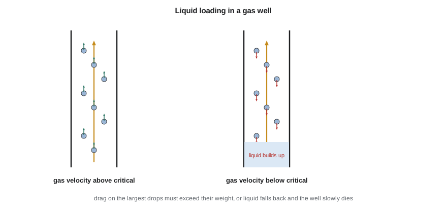
The symptoms are characteristic. The production becomes erratic, often with cycles in which the well slowly loads, then heads as accumulated gas pushes a slug of liquid out. The casing pressure rises relative to the tubing pressure, because the casing annulus has a gas column while the tubing has a heavier mixed column. Liquid production at the separator becomes irregular. The decline curve steepens suddenly, departing from the trend that the reservoir would justify. A flowing pressure survey or fluid level shows a liquid column near the bottom of the well.
Liquid loading matters because it strands reserves. A loaded well produces at a much higher bottomhole pressure than it needs to, so it abandons gas that it could otherwise recover. For low-permeability wells, liquid that falls back can also re-enter the rock and block it, a form of water block that may take months to clean up.
Turner's critical velocity
In 1969 Turner, Hubbard and Dukler analyzed field data from gas wells and proposed that the controlling mechanism is the lifting of the largest droplets. A droplet in a gas stream is held up by drag and pulled down by its weight. Large droplets are broken up by the gas, and the largest stable droplet is set by a balance between the gas's dynamic pressure and the liquid's surface tension, expressed as a critical Weber number. Combining the two balances gives a critical velocity above which the gas can carry the largest droplets.
Turner found that the field data fitted better if the velocity was raised by about 20 percent, giving a constant of about 1.91, and that version is still widely quoted. Later, Coleman and colleagues analyzed wells with lower wellhead pressures and found that the original value without the 20 percent adjustment fitted better at pressures below about 500 psi. Many companies use Turner's value with the adjustment as a conservative screen and Coleman's as a best estimate. Other authors have since proposed models based on the liquid film rather than droplets, which predict loading at somewhat different rates. All these models are approximate; their value lies in screening wells and comparing remedies.
The critical velocity converts to a critical rate by multiplying by the flow area and converting the gas volume to standard conditions. It is usually evaluated at the wellhead. There the gas density is lowest, which raises the critical velocity, but the actual velocity is highest; most analyzes find that the critical rate is largest, and therefore controlling, at the wellhead in vertical wells with constant tubing size. In wells with tapered strings or with the tubing set high above the perforations, the bottom of the tubing or the casing below it can control instead.
# Liquid loading in a gas well: Turner's critical velocity and critical rate, checked at the wellhead
import math
SI = False
if SI:   # Birch Coulee gas well 100/10-09; kPa and m3/d
    cases = [("today, 60.3 mm tubing, 1,800 kPa wellhead", 1800.0, 1.995), ("compression to 900 kPa wellhead", 900.0, 1.995),
             ("velocity string, 38.1 mm coiled tubing", 1800.0, 1.25)]
    rate_now = 12000.0
    p_to_psia = lambda p: p * 0.145038 + 14.7; q_show = lambda mm: f"{mm * 1e6 / 35.3147:8,.0f} m3/d"
    now = f"{rate_now:,.0f} m3/d"; rate_mm = rate_now * 35.3147 / 1e6
else:    # Birch Coulee gas well 10-9; psi and Mscf/d
    cases = [("today, 2-3/8 in tubing, 260 psi wellhead", 260.0, 1.995), ("compression to 130 psi wellhead", 130.0, 1.995),
             ("velocity string, 1-1/2 in coiled tubing", 260.0, 1.25)]
    rate_now = 420.0
    p_to_psia = lambda p: p + 14.7; q_show = lambda mm: f"{mm * 1000:8,.0f} Mscf/d"
    now = f"{rate_now:,.0f} Mscf/d"; rate_mm = rate_now / 1000
T, z, sg = 520.0, 0.95, 0.65          # wellhead temperature 60 F (520 R), z, gas gravity
sigma, rho_l = 60.0, 67.0             # water: surface tension dyn/cm, density lbm/ft3
print(f"current rate {now}")
for name, p, d_in in cases:
    P = p_to_psia(p)
    rho_g = 2.7 * sg * P / (z * T)                                  # lbm/ft3
    vc = 1.593 * sigma ** 0.25 * (rho_l - rho_g) ** 0.25 / rho_g ** 0.5   # ft/s, without the 20% allowance
    A = math.pi * (d_in / 12) ** 2 / 4
    qc = 3.067 * P * vc * A / (T * z)                                # MMscf/d
    state = "unloads" if rate_mm > qc else "loads up"
    print(f"   {name:45s} critical velocity {vc:4.1f} ft/s, critical rate {q_show(qc)}  -> {state}")
print(f" {'':45s} with Turner's 20% allowance: {q_show(qc * 1.2)}")current rate 420 Mscf/d
today, 2-3/8 in tubing, 260 psi wellhead critical velocity 12.8 ft/s, critical rate 474 Mscf/d -> loads up
with Turner's 20% allowance: 568 Mscf/d
compression to 130 psi wellhead critical velocity 17.7 ft/s, critical rate 344 Mscf/d -> unloads
with Turner's 20% allowance: 413 Mscf/d
velocity string, 1-1/2 in coiled tubing critical velocity 12.8 ft/s, critical rate 186 Mscf/d -> unloads
with Turner's 20% allowance: 223 Mscf/dThe program shows that the 10-9 gas well, at 420 Mscf/d, is below its critical rate of about 474 Mscf/d in 2-3/8 in tubing at 260 psi wellhead pressure, so it is loading, as Wes reported. Lowering the wellhead pressure to 130 psi with a compressor raises the critical velocity but lowers the gas density, and the net effect is to cut the critical rate to about 344 Mscf/d, below the well's rate. A velocity string of 1-1/2 in coiled tubing would cut the critical rate to about 186 Mscf/d, giving the well years of unloaded flow as it declines.
Remedies for liquid loading
The remedies all work by either raising the gas velocity, lowering the critical velocity, or removing the liquid by other means.
Smaller tubing or a velocity string. Reducing the flow area raises the velocity for the same rate. A velocity string, usually coiled tubing hung inside the existing tubing, is cheap to install and needs no energy. The penalty is higher friction, which reduces the rate the well can deliver at high flow, so velocity strings suit wells that are already declining. The program shows how much smaller the critical rate becomes.
Lower wellhead pressure. Compression at the wellhead or the field reduces the backpressure on the well, raising the rate from the reservoir and lowering the critical rate. Compression also lets the well produce down to a lower abandonment pressure, so it adds reserves. It costs capital, fuel or power, and maintenance, and it is usually justified for groups of wells rather than single wells.
Plunger lift. A free-traveling plunger rides up and down the tubing, using the well's own gas to push a slug of liquid to surface each cycle and preventing liquid from falling back. Plunger lift is cheap and needs no outside energy, and it is the most common remedy for loading gas wells with moderate liquid rates. Lesson 10 covers its design.
Foam. Surfactants injected down a capillary string or dropped as soap sticks reduce the surface tension and create a foam that the gas can carry at much lower velocities. Foaming works well with water but less well with condensate, which tends to break foam.
Pumping and gas lift. For wells with high liquid rates, a rod pump or small electric submersible pump can remove liquid from below the perforations, letting the gas flow up the annulus. Gas lift injects extra gas to raise the velocity. These are more expensive and are used when liquid rates are too high for plunger lift.
In horizontal gas wells the problem is harder. Liquid collects in low spots along an undulating lateral and in the curve, where the inclination makes the film drain more easily than in a vertical pipe. Studies of inclined flow suggest that the critical rate peaks at moderate inclinations of about 30 to 60 degrees from vertical, so the curve section, not the wellhead, may control. Many operators therefore set the end of the tubing low in the curve, or run plunger or gas lift systems designed for deviated wells.
Intermittent production. Some operators simply shut the well in periodically, letting pressure build so that the next flow period can unload the accumulated liquid. This is the crudest method, and automated timers or pressure controllers make it more effective, but it loses production during each shut-in.
Choosing a remedy
Marisol's team usually works through the options in order of cost. For the 10-9 gas well, the analysis favors a plunger now, because the well still has enough gas and pressure to drive one, with a velocity string held in reserve. The gathering company is planning a compressor station for the Birch Coulee gas pool in two years, which would lower every well's wellhead pressure and push the critical rates down further. Ethan recommends installing the plunger, monitoring tubing and casing pressures to confirm that it keeps the well unloaded, and re-evaluating when the compressor arrives.
Worked problem
Is a well near loading?
A gas well with 2-3/8 in tubing (ID 1.995 in) flows at a wellhead pressure of 300 psia and 520 °R, with z = 0.95 and gas gravity 0.65. Water is produced. Estimate the critical rate with Coleman's coefficient.
Show solution
- Gas density = 2.7 × 0.65 × 300/(0.95 × 520) = 1.07 lbm/ft³.
- Critical velocity = 1.593 × 60^0.25 × (67 − 1.07)^0.25/1.07^0.5 = 1.593 × 2.783 × 2.850/1.034 = 12.2 ft/s.
- Flow area = π × (1.995/12)²/4 = 0.0217 ft².
- Critical rate = 3.067 × 300 × 12.2 × 0.0217/(520 × 0.95) = 0.49 MMscf/d, or about 490 Mscf/d (about 13,900 m³/d).
Answer: A well producing less than about 490 Mscf/d at these conditions will tend to load; with Turner's 20 percent allowance the screen rises to about 590 Mscf/d.
Common mistakes
MistakeTreating erratic gas well production as a reservoir problem.
InsteadCheck for liquid loading first: casing-tubing pressure difference, heading and a steepened decline.
MistakeAssuming lower wellhead pressure always raises the critical rate.
InsteadIt lowers the critical rate, because the gas density falls faster than the critical velocity rises.
MistakeInstalling a velocity string too early.
InsteadWait until the well's rate approaches the critical rate; earlier, friction costs production.
MistakeUsing foam in wells with high condensate cuts.
InsteadCondensate breaks foam; consider plunger lift or pumping instead.
MistakeUsing a single critical-rate model as an exact boundary.
InsteadTreat the result as a screen with a margin and confirm with field data.
Summary and key terms
- Gas wells produce water and condensate that must be carried to surface.
- Liquid loading occurs when the gas velocity falls below what is needed to lift the largest droplets.
- Symptoms include heading, a rising casing-tubing pressure difference and a sudden steepening of the decline.
- Turner's critical velocity screens wells for loading; Coleman's version fits low-pressure wells.
- Remedies include velocity strings, compression, plunger lift, foam and pumping.
- Loading strands reserves, so timely remedies add recovery as well as rate.
- Liquid loading
- Accumulation of liquid in a gas well when gas velocity is too low to lift it.
- Critical velocity
- The minimum gas velocity needed to carry the largest liquid droplets upward.
- Heading
- Cyclic production in which a well slowly loads and then blows out a slug of liquid.
- Velocity string
- Smaller tubing, usually coiled tubing, hung inside the production tubing to raise gas velocity.
- Foam lift
- Using surfactants to reduce surface tension so gas can carry liquid at lower velocity.
- Weber number
- A ratio of inertial to surface-tension forces that sets the largest stable droplet size.
Practice problems
Work each problem on paper first, then reveal the answer to check.
Why does the casing pressure rise when a gas well loads?
Show answer
The tubing column becomes heavier with liquid while the annulus still holds gas.
What happens to the critical rate if the tubing diameter is halved?
Show answer
It falls to about a quarter, because it is proportional to the flow area.
Why is condensate harder to foam than water?
Show answer
Condensate breaks foam.
Name a remedy that needs no outside energy.
Show answer
A velocity string or a plunger.
Lesson quiz · 5 questions
Score 60% or more to complete this lesson.
Create a free account to save your progress, take quizzes and earn a certificate.