
PET-340 · Lesson 11 of 12 · 19 min
Surface facilities, produced water and emissions
Sofia Reyes, the facilities engineer, joins Ethan at the Tamarack pad facility to walk the equipment that will receive the 4-22H's production for the next twenty years. 'Everything you do downhole ends up here,' she says. 'If you double the water rate, I need treater capacity. If you keep the well on gas lift, I need compression. And every Mscf we flare counts against the state's gas capture goal and the federal methane rules. Production and facilities engineers have to plan together.'
This lesson covers the main surface facilities for oil and gas wells, the sizing of separators, the treatment of oil emulsions and produced water, flow assurance problems such as corrosion, scale, paraffin and hydrates, and the rules on flaring, venting and methane emissions in Canada and the United States.
What a facility does
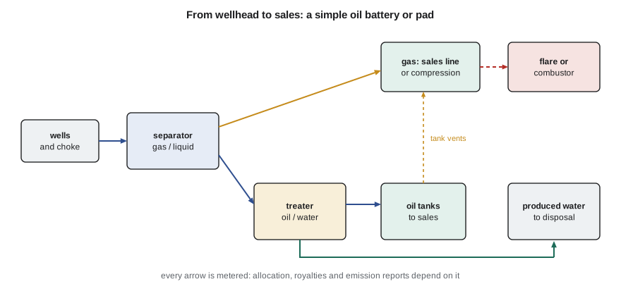
A production facility, called a battery in Canada and often a tank battery or pad facility in the United States, receives the mixed stream from one or more wells and turns it into saleable oil, saleable or usable gas, and water ready for disposal or injection. The typical sequence is a separator to split gas from liquid, a treater to break oil-water emulsions and remove water from the oil, storage tanks for oil, gas measurement and compression, and water storage and pumps. Each stream is measured for sales, royalties and regulatory reports. Larger fields have central facilities fed by gathering systems, with gas sent to a processing plant that removes liquids, water and sour components.
Separators
A separator is a pressure vessel in which gas and liquid are given time and space to part. Most separators have four sections: an inlet device that knocks the momentum out of the incoming stream and makes a first split; a gravity settling section where droplets fall out of the gas; a mist extractor, a mesh pad or vane pack that captures the fine droplets that remain; and a liquid collection section where gas bubbles rise out of the liquid. Two-phase separators split gas from total liquid; three-phase separators also split oil from water, using weirs or interface controls.
Separators are sized for two duties. The gas capacity is set by the velocity at which the largest droplets that must be captured can still settle against the upward gas flow. The Souders-Brown equation expresses this allowable velocity with an empirical coefficient K that depends on the vessel type and mist extractor.
The liquid capacity is set by retention time: the liquid must stay in the vessel long enough for gas to break out and, in three-phase separators, for oil and water to separate. Typical retention times are one to three minutes for two-phase separation of light oil and five to ten minutes or more for three-phase separation or foamy, viscous oils. The vessel must also hold slugs arriving from the flowline without flooding the gas outlet, which often controls the size more than steady flow does.
# Surface facilities: separator gas capacity (Souders-Brown) and liquid retention, treater heat duty,
# and an emissions check for the new well
import math
SI = False
if SI:   # 04-22 test separator at the Tamarack battery; SI throughout
    qg, ql, qo, qw, p, T = 5600.0, 66.0, 52.0, 14.0, 550.0, 288.0   # m3/d, kPa (gauge), K
    vent, ch4 = 120.0, 0.72                                          # tank-flash gas vented, m3/d; methane fraction
    sl = lambda m: f"{m:,.2f} m"; sv = lambda v: f"{v:,.2f} m3"; sq = lambda x: f"{x:,.0f} m3/d"
    sk = lambda kw: f"{kw:,.0f} kW"
else:    # 4-22H pad separator; computed in SI, shown in field units
    qg, ql, qo, qw, p, T = 900 * 28.317, 1610 / 6.2898, 1050 / 6.2898, 560 / 6.2898, 160 * 6.89476, 290.0
    flared, goal = 70.0, 0.91                                        # Mscf/d flared when the gas line is down part of the month
    sl = lambda m: f"{m / 0.3048:,.1f} ft"; sv = lambda v: f"{v * 6.2898:,.0f} bbl"; sq = lambda x: f"{x * 6.2898:,.0f} bbl/d"
    sk = lambda kw: f"{kw * 3412 / 1e6:,.2f} MMBtu/h"
P = p + 101.325
rho_g = P * 1000 * 28.97 * 0.75 / (0.95 * 8314 * T)       # kg/m3, gas gravity about 0.75
rho_l = 870.0
K = 0.11                                                  # m/s, vertical separator with a mist extractor (typical range)
vt = K * math.sqrt((rho_l - rho_g) / rho_g)
qg_act = qg * (101.325 / P) * (T / 288.7) * 0.95 / 86400   # m3/s at separator conditions
D = math.sqrt(4 * qg_act / (math.pi * vt))
print(f"gas density {rho_g:.1f} kg/m3; allowable gas velocity {vt:.2f} m/s; minimum vessel diameter for gas {sl(D)}")
for minutes in (3, 10):
    print(f"   liquid volume for {minutes:2d} min retention: {sv(ql * minutes / 1440)}")
duty = (qo * 870 * 2.0 + qw * 1050 * 4.18) * 1000 * (60 - 15) / 86400 / 1000   # kW to heat from 15 to 60 C (kJ/kg.K)
print(f"treater heat to warm the emulsion by 45 degrees C (81 F): about {sk(duty)} before heat recovery")
if SI:
    intensity = vent * ch4 / qg
    print(f"tank vent {sq(vent)} at {ch4:.0%} methane = {intensity:.2%} of produced gas as vented methane")
    print("   the federal performance pathway cited for production facilities is 0.20%; vapor recovery or combustion is needed")
else:
    prod = 900.0; cap = (prod - flared) / prod
print(f"gas capture {cap:.1%} (produced {prod:,.0f} Mscf/d, flared {flared:,.0f}) against the state goal of {goal:.0%}")gas density 11.4 kg/m3; allowable gas velocity 0.95 m/s; minimum vessel diameter for gas 0.6 ft liquid volume for 3 min retention: 3 bbl liquid volume for 10 min retention: 11 bbl treater heat to warm the emulsion by 45 degrees C (81 F): about 1.21 MMBtu/h before heat recovery gas capture 92.2% (produced 900 Mscf/d, flared 70) against the state goal of 91%
For the 4-22H alone, the gas capacity barely matters: a vessel well under a foot across could carry the gas. The liquid duty is also modest, about 11 bbl for ten minutes of retention. Real separators are much larger, because they serve several wells, must absorb slugs and flowback surges, and come in standard sizes. Sofia's pad separator has ample room. The heater-treater is a different matter: warming the emulsion by about 45 °C (81 °F) needs about 1.2 MMBtu/h before heat recovery, and Bakken winters put the burner close to its limit.
Treating oil and water
Water produced with oil often forms an emulsion, droplets of water dispersed in the oil, stabilized by natural surfactants, fine solids and asphaltenes. Sales contracts limit the water and sediment in crude, often to less than 0.5 to 1 percent. Heater-treaters break emulsions by combining heat, which lowers oil viscosity and weakens the films around droplets; demulsifier chemicals, which displace the natural stabilizers; time; and sometimes electrostatic grids that make droplets coalesce. Free-water knockouts upstream remove water that separates easily and save heating it.
Produced water is the largest volume stream in most mature oil fields, often several barrels or cubic meters of water for each one of oil. It carries dissolved salts, sometimes at concentrations several times that of seawater in basins such as the Williston, along with dispersed oil, solids, bacteria and naturally occurring radioactive material. It is treated to remove oil and solids and then either injected into the reservoir for pressure maintenance or waterflooding, or injected into approved disposal zones. Discharge to surface water is generally not permitted onshore. Water handling is often the main constraint on a field's capacity, and its cost per barrel can exceed the cost of lifting the oil.
Flow assurance
Flow assurance covers the problems that restrict flow in wells, lines and facilities, and the production engineer works on them daily.
Corrosion comes mainly from carbon dioxide forming carbonic acid in water, hydrogen sulfide causing pitting and cracking, oxygen entering through vents or injection water, and bacteria. It is managed with corrosion-resistant materials, coatings, chemical inhibitors injected continuously or in batches, cathodic protection for buried lines, and monitoring with coupons and probes. Under-deposit corrosion beneath scale or sludge is a common cause of flowline leaks.
Scale forms when dissolved minerals precipitate as pressure and temperature change or when incompatible waters mix: calcium carbonate where CO₂ comes out of solution, barium and strontium sulfate where sulfate-rich injection water meets barium-rich formation water, and in some fields, halite from very salty brines. Scale chokes perforations, pumps, tubing and valves. It is prevented with inhibitors, sometimes squeezed into the formation, and removed with acid or mechanical milling. Bakken wells are known for halite deposition, and operators often inject fresh water continuously to keep salt in solution.
Paraffin and asphaltenes deposit from crude oils as they cool or as pressure falls. Paraffin forms waxy deposits in tubing and flowlines below the oil's cloud point, especially in cold climates. Remedies include hot oiling, scraping with mechanical cutters, chemical inhibitors and insulated or heated lines. Asphaltenes come out of solution near the bubble point and are harder to treat.
Hydrates are ice-like solids of water and light gases that form at high pressure and low temperature, often in gas lines and chokes in winter. They are prevented with methanol or glycol injection, heating or keeping the water out.
Sand and solids erode chokes and pumps and fill separators. Good completion practice limits them, and facilities use sand traps, desanders and cyclones where they persist.
Flaring, venting and methane
Gas that cannot be sold or used is either flared, burned at a flare stack or enclosed combustor, or vented directly to the air. Methane is a powerful greenhouse gas, so venting is now tightly restricted in both countries, and flaring is limited by gas conservation rules. Both countries have committed to deep cuts in oil and gas methane emissions.
In North Dakota, the North Dakota Industrial Commission (NDIC) regulates flaring through Order 24665 and its guidance. Its gas capture goals rose in steps from 74 percent in 2014 to 91 percent from 1 November 2020, and operators that miss the goals must file a gas capture plan with each application for a drilling permit. Federally, the Environmental Protection Agency's 2024 methane and VOC standards for oil and gas (subparts OOOOb for new sources and OOOOc for existing sources) cover leaks, storage vessels, process controllers and flares. In 2025 the agency extended many compliance deadlines; under its November 2025 final rule, most OOOOb requirements apply from 22 January 2027, and state plans for existing sources are due the same day. These rules continue to change, so production engineers follow the current version closely.
The program shows that the 4-22H's pad captured about 92 percent of its gas last month, above the 91 percent goal, but only because the gathering line was down for just part of the month. A longer outage would push the pad below the goal. Sofia's pad compressor project would let the pad keep selling gas when the line pressure rises, and would also supply gas lift.
Leak detection and measurement
Much of the methane from oil and gas operations comes not from routine venting but from leaks and malfunctions: stuck dump valves on separators that let gas reach tanks, open thief hatches, leaking compressor seals and pneumatic controllers that bleed gas. Leak detection and repair (LDAR) programs use optical gas imaging cameras, handheld analyzers and, increasingly, continuous sensors, aircraft and satellites to find leaks so they can be fixed quickly. Replacing gas-driven pneumatic devices with electric or instrument-air ones removes a large source of routine emissions. Production engineers contribute by designing wells and facilities that do not need to vent, by setting separator and tank pressures that limit flash losses, and by tracking emissions as closely as production.
Worked problem
Sizing a separator for gas
A vertical separator handles gas with a density of 10 kg/m³ and oil of 850 kg/m³, with K = 0.11 m/s. The actual gas flow at separator conditions is 0.05 m³/s. Find the minimum diameter for gas capacity.
Show solution
- Allowable velocity: vt = 0.11 × √((850 − 10)/10) = 0.11 × 9.17 = 1.01 m/s.
- Required area: A = 0.05/1.01 = 0.0495 m².
- Diameter: D = √(4 × 0.0495/π) = 0.25 m (about 10 in).
- A larger vessel is then chosen for liquid retention and slugs.
Answer: In oil service, liquid retention and slug handling usually govern; gas capacity governs in gas-dominated service.
Common mistakes
MistakeSizing a separator for steady flow only.
InsteadAllow for slugs, flowback surges and future wells.
MistakeChanging a well's lift or rates without telling facilities.
InsteadCheck separator, treater, water and compression capacity first.
MistakeTreating produced water as a minor stream.
InsteadPlan its handling and disposal cost; it often controls field capacity.
MistakeIgnoring tank flash and pneumatic devices in emission estimates.
InsteadInclude all sources and use leak detection to find malfunctions.
MistakeRelying on an old version of methane rules.
InsteadCheck the current federal, provincial or state requirements before designing.
Summary and key terms
- Facilities separate gas, oil and water, treat each stream and measure it.
- Separators are sized for gas velocity, liquid retention time and slugs.
- Heater-treaters break emulsions with heat, chemicals, time and electrostatic grids.
- Produced water is often the largest stream and is injected for disposal or flooding.
- Flow assurance covers corrosion, scale, paraffin, asphaltenes, hydrates and sand.
- Flaring, venting and methane emissions are tightly regulated and changing in both countries.
- Battery
- A surface facility that separates, treats, stores and measures production from wells.
- Souders-Brown equation
- An expression for the allowable gas velocity in a separator.
- Retention time
- The average time liquid stays in a vessel.
- Emulsion
- A dispersion of one liquid in another, such as water droplets in oil.
- Flow assurance
- Keeping fluids flowing by preventing corrosion, deposits and blockages.
- Vapor recovery unit
- A compressor that captures gas from tanks and sends it to sales.
- LDAR
- Leak detection and repair programs that find and fix emissions from equipment.
Practice problems
Work each problem on paper first, then reveal the answer to check.
Why does liquid retention usually govern separator size in oil service?
Show answer
Gas capacity needs only a small diameter, but liquid needs time and slug volume.
What causes calcium carbonate scale in a producing well?
Show answer
CO₂ leaving solution as pressure falls raises the pH and precipitates carbonate.
Name two ways to control paraffin.
Show answer
Hot oiling and chemical inhibitors, or mechanical scraping.
Why is replacing gas-driven pneumatic controllers an emissions measure?
Show answer
They bleed natural gas, mostly methane, to the air in normal operation.
Lesson quiz · 5 questions
Score 60% or more to complete this lesson.
Create a free account to save your progress, take quizzes and earn a certificate.