
PET-310 · Lesson 5 of 12 · 19 min
Drilling hydraulics
The rig's mud pumps can deliver only so much pressure, and every bit of it is spent somewhere between the pump and the flowline. Marcus asks Ethan to work out where it goes for the 3-22H well at the end of each section. 'Hydraulics answers four questions,' he says. 'Can the pumps deliver the flow rate we need to clean the hole? How much energy reaches the bit? What pressure does the circulating mud put on the open hole? And how fast can we move pipe without surging or swabbing the well?'
The circulating system as a pressure budget
The pressure the pump must deliver, the standpipe pressure, is the sum of the frictional pressure losses around the circuit: through the surface equipment, inside the drill pipe and BHA, across the bit nozzles, and back up the annulus. Hydrostatic pressure cancels around the loop, because the fluid goes down and comes back up, as long as the mud density is the same inside and outside the string. Downhole motors and MWD tools add their own pressure drops.
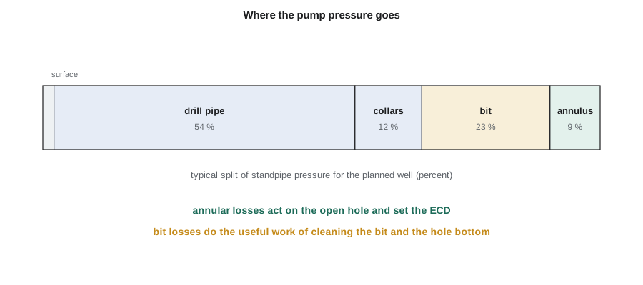
The pressure losses inside the pipe and annulus are wasted as heat, while the bit pressure drop does useful work: it creates the jets that clean the bit and the bottom of the hole. A classic aim of hydraulics design was to put about half to two-thirds of the pump pressure across the bit. In long horizontal wells this is seldom possible, because the pipe losses grow with length, and the priority shifts to having enough flow rate for hole cleaning within the pump's pressure limit.
Flow regimes and frictional losses
Mud in the drill pipe usually flows in turbulent flow, where losses rise roughly with the 1.75 power of velocity. In the annulus, where the area is larger and the velocity lower, flow is often laminar, and the Bingham plastic model gives losses made up of a viscous term proportional to velocity and plastic viscosity and a yield term proportional to yield point. The transition is judged with a Reynolds number adapted for non-Newtonian fluids. API recommended practice 13D gives detailed methods for the rheology and hydraulics of drilling fluids, generally based on the Herschel-Bulkley or power-law models; the simpler Bingham field equations used here give the right orders of magnitude.
In this field form, pressure is in psi, PV in cP, YP in lb/100 ft², velocity in ft/s, length in ft and diameters in inches. Two consequences matter. Annular losses rise with flow rate and with yield point, so a thick mud raises the pressure on the open hole. And annular losses rise sharply as the clearance narrows, which is why slim holes and long laterals with large pipe can have high equivalent circulating densities.
Bit hydraulics
The bit has nozzles, also called jets, whose sizes are given in 32nds of an inch. Their total flow area (TFA) sets the bit pressure drop for a given flow rate and mud weight. The pressure drop across the nozzles converts to jet velocity and hydraulic power at the bit. Two criteria are used to optimize nozzle size: maximum hydraulic horsepower at the bit, which favors a bit pressure drop of about 65 percent of the pump pressure, and maximum jet impact force, which favors about 48 percent. The hydraulic horsepower per square inch of hole area (HSI) is a common measure of cleaning energy.
Here Q is in gallons per minute, MW in ppg, the nozzle area An in square inches and pressure in psi; the constant includes a nozzle discharge coefficient of 0.95. Jet velocity is about 0.32 Q/An in ft/s.
Equivalent circulating density
When mud is circulating, the pressure at any point in the open hole is the hydrostatic pressure plus the frictional pressure loss in the annulus above that point. Expressed as a density, this is the equivalent circulating density (ECD). The ECD, not the static mud weight, must stay below the fracture gradient at the weakest point of the open hole, usually just below the last casing shoe, and it must be considered with the extra load from cuttings in the annulus. In long horizontal wells the annular friction acts over the full measured depth while the hydrostatic pressure depends only on the true vertical depth, so ECD rises steadily as the lateral is drilled.
# Circulating system hydraulics: pressure losses (Bingham plastic), bit hydraulics and ECD
import math
SI = False
pv, yp = 16.0, 14.0                                    # cP, lb/100 ft2
if SI:
    mw, Q, hole, dp_od, dp_id, dc_od, dc_id = 1150/119.826, 1.4/0.0037854, 200/25.4, 4.0, 3.34, 6.25, 2.81
    md, tvd, Ldc, noz = 3260/0.3048, 1560/0.3048, 540.0, [12, 12, 12, 12]   # four 12/32 in nozzles
else:
    mw, Q, hole, dp_od, dp_id, dc_od, dc_id = 10.2, 550.0, 8.75, 4.5, 3.826, 6.5, 2.81
    md, tvd, Ldc, noz = 10720.0, 10450.0, 540.0, [13, 13, 13, 13, 13]
Ldp = md - Ldc
def pipe_dp(L, d):                                     # turbulent flow inside pipe (common field form)
    v = Q / (2.448 * d * d)
    return mw ** 0.75 * v ** 1.75 * pv ** 0.25 * L / (1800 * d ** 1.25)
def ann_dp(L, d2, d1):                                 # laminar Bingham plastic flow in the annulus
    v = Q / (2.448 * (d2 * d2 - d1 * d1))
    return pv * v * L / (1000 * (d2 - d1) ** 2) + yp * L / (200 * (d2 - d1))
surf = 50.0                                            # surface lines, standpipe and top drive (psi, illustrative)
p_dp, p_dc = pipe_dp(Ldp, dp_id), pipe_dp(Ldc, dc_id)
a_dp, a_dc = ann_dp(Ldp, hole, dp_od), ann_dp(Ldc, hole, dc_od)
tfa = sum(math.pi / 4 * (n / 32) ** 2 for n in noz)
p_bit = Q * Q * mw / (12032 * tfa * tfa)               # discharge coefficient 0.95 included
total = surf + p_dp + p_dc + a_dp + a_dc + p_bit
hhp = p_bit * Q / 1714; hsi = hhp / (math.pi / 4 * hole ** 2)
vn = 0.3208 * Q / tfa; jif = 0.01823 * 0.95 * Q * math.sqrt(mw * p_bit)
ecd = mw + (a_dp + a_dc) / (0.052 * tvd)
k = 6.894757
rows = [("surface equipment", surf), ("inside drill pipe", p_dp), ("inside collars", p_dc), ("bit nozzles", p_bit), ("annulus, collars", a_dc), ("annulus, drill pipe", a_dp)]
for n_, v in rows:
    print(f"{n_:22s} {v*k:8,.0f} kPa" if SI else f"{n_:22s} {v:8,.0f} psi")
print(f"standpipe pressure {total*k:,.0f} kPa; bit share {100*p_bit/total:.0f} percent" if SI else f"standpipe pressure {total:,.0f} psi; bit share {100*p_bit/total:.0f} percent")
print(f"TFA {tfa*645.16:.0f} mm2, nozzle velocity {vn*0.3048:.0f} m/s, HSI {hsi*0.1156:.2f} kW/cm2 ({hsi:.2f} hp/in2), jet impact {jif*4.448:,.0f} N" if SI else f"TFA {tfa:.3f} in2, nozzle velocity {vn:.0f} ft/s, HSI {hsi:.2f} hp/in2, jet impact {jif:,.0f} lbf")
print(f"ECD {ecd*119.826:,.0f} kg/m3 against static {mw*119.826:,.0f} kg/m3" if SI else f"ECD {ecd:.2f} ppg against static {mw:.1f} ppg")surface equipment 50 psi inside drill pipe 1,436 psi inside collars 330 psi bit nozzles 611 psi annulus, collars 28 psi annulus, drill pipe 204 psi standpipe pressure 2,658 psi; bit share 23 percent TFA 0.648 in2, nozzle velocity 272 ft/s, HSI 3.26 hp/in2, jet impact 752 lbf ECD 10.63 ppg against static 10.2 ppg
At the end of the intermediate section, circulating 550 gpm of 10.2 ppg mud, the standpipe pressure is about 2,660 psi, of which about 23 percent is across the five 13/32 in nozzles, giving an HSI of 3.3 hp/in². The annular losses of about 230 psi raise the ECD to about 10.6 ppg. In the 6 in lateral, the narrower annulus and longer length will push the ECD higher, which Ethan flags for the lateral hydraulics plan.
Hole cleaning
Cuttings must be carried out as fast as they are made. In vertical holes, annular velocity and the mud's carrying capacity (its yield point and low-shear rheology) do most of the work. In deviated and horizontal holes cuttings settle quickly to the low side and form a bed. The worst range is roughly 35 to 60 degrees of inclination, where beds can slide down the hole and pack off around the BHA. In the lateral, beds are removed mainly by flow rate and by pipe rotation, which stirs the bed into the flowing mud. Signs of poor hole cleaning include rising torque and drag, overpull on connections, erratic pressure and reduced cuttings at the shakers compared with the drilled volume.
Good practice in horizontal wells is to keep the flow rate as high as the ECD and pump limits allow, rotate the pipe at a good speed, circulate the hole clean before trips, and track cuttings returns against the drilled volume. Sweeps of high- or low-viscosity fluid are used but are less effective in the lateral than rotation and flow rate.
Surge and swab
Moving pipe moves mud. Running pipe into the hole pushes mud up the annulus and raises bottomhole pressure, a surge, which can fracture a weak formation and cause losses. Pulling pipe drags mud with it and lowers bottomhole pressure, a swab, which can draw formation fluid into the well and start a kick. Both are calculated like annular pressure losses, using an effective velocity based on the pipe speed and whether the pipe is open or closed at the bottom. Tripping speed limits are set from these calculations, especially in narrow mud-weight windows, and modern rigs can enforce them automatically.
Worked problem
Bit pressure drop and HSI
Mud of 10.0 ppg is pumped at 500 gpm through three 14/32 in nozzles in an 8-3/4 in bit. Find the TFA, the bit pressure drop, the hydraulic horsepower at the bit and the HSI.
Show solution
- Area of one nozzle = (π/4)(14/32)² = 0.1503 in²; TFA = 3 × 0.1503 = 0.451 in².
- Δpb = 500² × 10.0/(12,032 × 0.451²) = 2,500,000/2,447 = 1,022 psi.
- HHPb = 1,022 × 500/1,714 = 298 hp.
- Hole area = (π/4)(8.75)² = 60.1 in²; HSI = 298/60.1 = 4.96 hp/in².
Answer: TFA 0.451 in², bit pressure drop about 1,020 psi, about 300 hp at the bit and an HSI near 5.
Pumps and their limits
A triplex mud pump delivers a volume per stroke set by its liner diameter and stroke length, multiplied by a volumetric efficiency of about 95 percent. Smaller liners give less flow per stroke but allow higher pressure, because the force on the piston is limited. The pump's hydraulic power, pressure times flow rate, is limited by its input power. The planned flow rate and the calculated standpipe pressure for each section must fall inside the pump's operating envelope with a margin, usually by choosing the liner size. In the 3-22H well, the pressure grows as the lateral lengthens, so the liners chosen for the lateral must allow the highest pressure planned at total depth.
Pump output is also the basis of the well control calculations in lesson 7, where the number of strokes needed to pump kill mud to the bit is calculated from the string's internal volume and the pump output per stroke. Accurate pump output figures matter for both.
Checking the model against the rig
Hydraulics calculations are checked against measured standpipe pressure while drilling. If the measured pressure is much higher than predicted, the cause may be cuttings loading in the annulus, a partly plugged nozzle or a change in mud properties; if it is lower, a washout in the string or a lost nozzle may be the cause. Some rigs measure annular pressure downhole with a pressure-while-drilling sensor in the BHA, which gives the actual ECD and shows cuttings loading and surge and swab directly. Marcus asks for that sensor in the 3-22H well's lateral BHA, so the ECD in the lateral is measured rather than estimated.
Common mistakes
MistakeUsing static mud weight to check fracture margins while drilling.
InsteadCheck the ECD, including cuttings load, against the fracture gradient.
MistakeAssuming more bit pressure is always better in long laterals.
InsteadFlow rate for hole cleaning, within pump and ECD limits, usually matters more.
MistakeTripping as fast as possible.
InsteadLimit speed to keep surge and swab pressures inside the mud-weight window.
MistakeRelying on sweeps alone to clean a lateral.
InsteadUse high flow rate and pipe rotation; track cuttings returns.
Summary and key terms
- Standpipe pressure is the sum of losses in the surface equipment, string, bit and annulus.
- Pipe flow is usually turbulent and annular flow often laminar; Bingham or more accurate models give the losses.
- Bit hydraulics are measured by bit pressure drop, jet velocity, hydraulic horsepower, HSI and jet impact force.
- ECD adds annular friction to hydrostatic pressure and must stay below the fracture gradient.
- In horizontal wells, flow rate and pipe rotation clean the hole; surge and swab limits govern tripping speed.
- Standpipe pressure
- The pressure delivered by the pumps, measured at the standpipe.
- Total flow area (TFA)
- The combined area of the bit nozzles.
- HSI
- Hydraulic horsepower at the bit per square inch of hole area.
- Equivalent circulating density (ECD)
- The effective density at a depth while circulating, including annular friction.
- Surge
- Pressure increase caused by running pipe into the hole.
- Swab
- Pressure reduction caused by pulling pipe out of the hole.
- Cuttings bed
- A layer of settled cuttings on the low side of a deviated hole.
Practice problems
Work each problem on paper first, then reveal the answer to check.
Annular losses are 300 psi at 10,000 ft TVD with 10.0 ppg mud. Find the ECD.
Show answer
10.0 + 300/(0.052 × 10,000) = 10.58 ppg.
Why does ECD rise as a lateral is drilled even though TVD stays the same?
Show answer
Annular friction grows with measured depth while hydrostatic pressure does not.
Which inclination range is hardest to clean, and why?
Show answer
About 35 to 60 degrees, where cuttings beds form and can slide downhole.
What can happen if pipe is pulled too fast?
Show answer
Swabbing lowers bottomhole pressure and may draw in formation fluid, starting a kick.
Lesson quiz · 5 questions
Score 60% or more to complete this lesson.
Create a free account to save your progress, take quizzes and earn a certificate.