
PET-310 · Lesson 10 of 12 · 18 min
Directional and horizontal drilling
The directional plan for the 3-22H well arrives from the directional drilling company: a table of measured depths, inclinations and azimuths, with the calculated positions. Marcus asks Ethan to check it independently. 'Directional drillers are very good,' he says, 'but every number that decides where the well goes, and whether it might hit another well on the pad, gets checked twice. And once we're drilling, you'll check the real surveys the same way, every stand.'
Why wells are steered
Wells are drilled directionally to reach targets offset from the surface location: under lakes, towns or protected land; from a pad holding many wells, which reduces surface disturbance, roads and pipelines; to follow a reservoir horizontally; to sidetrack around a fish (equipment lost in the hole); or to drill a relief well to intercept a blowing well. In tight-oil and shale development, pads of four to more than twenty horizontal wells are standard, so directional drilling is central to the whole development, not a special case.
Describing the well path
A well's position is measured at survey stations. At each station the MWD tool measures the inclination, the angle from vertical, and the azimuth, the compass direction of the hole's horizontal projection, measured clockwise from north. Measured depth comes from the length of pipe in the hole. From these three numbers at successive stations, the position of each station is calculated: its true vertical depth, its north and east coordinates relative to the surface location, and its vertical section, the horizontal distance along the planned direction. The curvature between stations is the dogleg, expressed as dogleg severity in degrees per 30 m or per 100 ft.
The industry standard calculation is the minimum curvature method, which assumes the path between two stations is a smooth circular arc. It uses the dogleg angle β between the two station directions and a ratio factor RF that converts the straight-line average into the arc.
The east displacement uses sines of the azimuths in place of the cosines. Dogleg severity is the dogleg angle scaled to the standard course length. Simpler methods, such as the tangential method, give large errors and are no longer used for well positions.
# Minimum curvature survey calculation: TVD, north, east, vertical section and dogleg severity
import math
SI = False
if SI:   # station measured depth (m), inclination (deg), azimuth (deg); planned azimuth 355 deg
    st = [(1388, 0.0, 0.0), (1418, 9.6, 354.0), (1448, 19.8, 355.5), (1478, 30.3, 355.0), (1508, 40.1, 356.0),
          (1538, 50.6, 355.0), (1568, 60.2, 354.5), (1598, 70.4, 355.5), (1628, 80.1, 355.0), (1658, 89.6, 355.0), (1700, 90.2, 355.2)]
    vsaz, unit, course = 355.0, "m", 30.0
else:    # feet; planned azimuth 180 deg (south lateral)
    st = [(9973, 0.0, 0.0), (10073, 11.8, 181.0), (10173, 23.9, 180.5), (10273, 36.2, 180.0), (10373, 48.1, 179.5),
          (10473, 60.3, 180.2), (10573, 72.0, 180.0), (10673, 84.1, 180.4), (10723, 89.8, 180.0), (10850, 90.3, 179.8)]
    vsaz, unit, course = 180.0, "ft", 100.0
tvd0 = st[0][0]
tvd, n, e = tvd0, 0.0, 0.0
print(f"   MD     inc     azi       TVD     north      east   vert sect   dogleg (deg/{course:.0f} {unit})")
r = math.radians
for (m1, i1, a1), (m2, i2, a2) in zip(st, st[1:]):
    cosb = math.cos(r(i2 - i1)) - math.sin(r(i1)) * math.sin(r(i2)) * (1 - math.cos(r(a2 - a1)))
    b = math.acos(max(-1.0, min(1.0, cosb)))
    rf = 1.0 if b < 1e-9 else 2 / b * math.tan(b / 2)
    dm = m2 - m1
    n += dm / 2 * (math.sin(r(i1)) * math.cos(r(a1)) + math.sin(r(i2)) * math.cos(r(a2))) * rf
    e += dm / 2 * (math.sin(r(i1)) * math.sin(r(a1)) + math.sin(r(i2)) * math.sin(r(a2))) * rf
    tvd += dm / 2 * (math.cos(r(i1)) + math.cos(r(i2))) * rf
    vs = n * math.cos(r(vsaz)) + e * math.sin(r(vsaz))
    dls = math.degrees(b) * course / dm
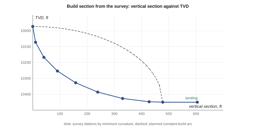
print(f"{m2:6.0f} {i2:7.1f} {a2:7.1f} {tvd:9.1f} {n:9.1f} {e:9.1f} {vs:10.1f} {dls:9.1f}")MD inc azi TVD north east vert sect dogleg (deg/100 ft) 10073 11.8 181.0 10072.3 -10.3 -0.2 10.3 11.8 10173 23.9 180.5 10167.3 -40.9 -0.5 40.9 12.1 10273 36.2 180.0 10253.7 -90.8 -0.7 90.8 12.3 10373 48.1 179.5 10327.7 -157.8 -0.4 157.8 11.9 10473 60.3 180.2 10386.1 -238.8 -0.2 238.8 12.2 10573 72.0 180.0 10426.5 -330.1 -0.4 330.1 11.7 10673 84.1 180.4 10447.1 -427.7 -0.7 427.7 12.1 10723 89.8 180.0 10449.8 -477.6 -0.9 477.6 11.4 10850 90.3 179.8 10449.7 -604.6 -0.7 604.6 0.4
The surveys through the build section show inclination rising by about 12 degrees every 100 ft, as planned, with dogleg severities from 11.4 to 12.3 degrees per 100 ft. The well lands at about 10,450 ft TVD with about 478 ft of vertical section, close to the planned arc. Ethan's numbers match the directional company's table to within a few tenths of a foot, which Marcus says is what he wants to see before signing it off.
Steering tools
Two main systems steer the bit. A steerable motor is a positive displacement mud motor with a small bend, typically 1 to 2 degrees, in its housing. To build or turn, the driller stops rotating the string and 'slides', pointing the bend in the desired direction, the toolface, while the motor turns the bit. To drill straight, the whole string is rotated, which averages out the bend. Sliding is slower and makes tortuous hole, and in long laterals friction makes it hard to transfer weight while sliding.
A rotary steerable system (RSS) steers while the whole string rotates, either by pushing against the wall with pads (push-the-bit) or by bending a shaft inside the tool (point-the-bit). RSS tools drill smoother holes with less tortuosity, clean the hole better because the pipe keeps rotating, and allow longer laterals, but cost more per day. Many operators use motors for the build and RSS for long laterals, or RSS throughout where the economics favor it.
Measurement while drilling and geosteering
MWD tools measure inclination with accelerometers and azimuth with magnetometers, and send the data to surface as pressure pulses in the mud column, or by electromagnetic telemetry in some land wells. Logging-while-drilling tools add gamma ray, resistivity, density and other logs, also transmitted in real time. Magnetic azimuth must be corrected for the declination at the location and for magnetic interference from the drill string; operators use models of the earth's field, and gyroscopic surveys where interference is severe, such as near other casing on a pad.
Geosteering uses real-time logs to keep the lateral in the best part of the target zone. A geologist compares the gamma ray and other logs with a model built from offset wells and the pilot or landing data, and recommends small changes in inclination to stay in the sweet spot. In thin targets, the zone may be only a few meters thick, so good geosteering decides much of the well's productivity.
Anti-collision
On pads, wells start a few meters apart, and in mature fields new wells pass near existing ones. Collision with a producing well could cause a blowout. Survey measurements have uncertainty, which grows with depth and depends on the tools and corrections used; it is described by an ellipsoid of uncertainty around each station, using industry error models. Anti-collision scans compute the separation factor, the center-to-center distance between wells divided by the combined uncertainty, and set rules: drilling continues normally above a threshold, with extra caution and surveys in a warning range, and stops or the well is redesigned below a minimum. Every directional plan includes an anti-collision report.
Worked problem
Dogleg severity between two stations
Two stations 100 ft apart have inclinations 20 and 26 degrees and azimuths 40 and 44 degrees. Find the dogleg angle and dogleg severity per 100 ft.
Show solution
- cos β = cos 6° − sin 20° sin 26° (1 − cos 4°) = 0.99452 − 0.34202 × 0.43837 × 0.00244 = 0.99416.
- β = arccos 0.99416 = 6.20°.
- Dogleg severity = 6.20 × 100/100 = 6.2 degrees per 100 ft.
Answer: About 6.2 degrees per 100 ft.
Limits of horizontal wells
Lateral lengths have grown from a few hundred meters to several kilometers. Limits come from torque and drag, which may prevent pushing the string or casing to the end (lesson 11); from hydraulics, because ECD rises with length (lesson 5); from hole cleaning; and from the completion, which must reach the toe. Smooth well paths with low tortuosity, good hole cleaning, lubricants, RSS tools and floating casing all help extend reach.
Planning the trajectory
A directional plan is built from straight and curved segments. The common profiles are the build-and-hold (or J) profile, which builds to a tangent angle and holds it to the target; the S profile, which builds, holds and drops back toward vertical; and the horizontal profile, which builds to about 90 degrees and holds. Horizontal wells often use two build sections with a short tangent between them, so the directional driller can adjust the landing depth after seeing the actual position of the target zone on the gamma ray log. The planned dogleg severity is chosen from the capability of the steering tools and from the limits of the casing and completion equipment that must pass through the curve.
Higher build rates shorten the curve and keep more of the well in the target, but they raise bending stresses in the pipe and casing, increase torque and drag and fatigue, and can make it harder to run the completion. Lower build rates give a smoother well but a longer curve, often through formations that are less stable. The 3-22H plan's build rate is a compromise based on the offset wells, which landed successfully at similar rates.
Survey frequency and quality
Surveys are usually taken at every connection in the build and lateral, every 30 m or 100 ft or so, and less often in vertical hole. More frequent surveys improve the position estimate in the build, where curvature is high. Each survey is checked against quality criteria: the measured gravity field and magnetic field strength and dip angle should match the expected values for the location, otherwise the survey may be affected by magnetic interference or a sensor problem. Many operators use corrections that combine measured and modeled magnetic fields to reduce uncertainty, and run a gyro survey through the vertical section where nearby casing distorts the magnetic field.
Tortuosity and its effects
A well that wanders around its planned path, with many small doglegs from sliding and correcting, is tortuous. Tortuosity increases torque and drag, makes casing harder to run, raises casing wear and makes completion and artificial lift equipment harder to place. It is measured by summing the absolute curvature along the well beyond what the plan required. Rotary steerable tools and careful steering practices reduce it, and Marcus sets a tortuosity target for the lateral in the drilling program alongside the target window for the geosteering.
Directional drilling in the field
On the rig, the directional driller works with the driller and the MWD operator. Each survey is checked, the position is projected ahead to the bit, and the next slide or steering setting is chosen to keep the well on plan. The plan has a tolerance, often a cylinder around the planned path or a window in the target zone, and corrections are made early and gently rather than late and sharply. In the lateral, the geologist's geosteering advice is weighed against the directional plan; small changes of a degree or less in inclination keep the bit in the best rock without creating sharp doglegs.
The surveys are sent to the operator in real time and become the well's official position record, submitted to the regulator after the well is finished. Accurate final surveys matter long after drilling: future wells on the pad will use them for anti-collision, and they are the record that shows where the well is under the land and mineral rights.
Common mistakes
MistakeUsing the tangential method for positions.
InsteadUse minimum curvature, the industry standard.
MistakeForgetting magnetic declination and interference.
InsteadCorrect azimuths to the reference north and use gyros where interference is high.
MistakeTreating survey positions as exact.
InsteadUse error models and separation factors for anti-collision.
MistakeSliding long distances in the lateral with a motor.
InsteadConsider RSS to reduce tortuosity and improve weight transfer and cleaning.
Summary and key terms
- Directional wells reach offset targets, allow pad drilling and follow reservoirs horizontally.
- Each survey station gives measured depth, inclination and azimuth; minimum curvature gives TVD, north, east and vertical section.
- Dogleg severity measures curvature per 30 m or 100 ft.
- Steerable motors steer by sliding; rotary steerable systems steer while rotating.
- MWD, LWD and geosteering keep the well in the target; anti-collision uses uncertainty models and separation factors.
- Inclination
- The angle of the wellbore from vertical.
- Azimuth
- The compass direction of the wellbore projection, measured clockwise from north.
- Minimum curvature method
- Survey calculation that assumes a circular arc between stations.
- Dogleg severity
- The rate of change of wellbore direction per standard length.
- Toolface
- The orientation of the bend or steering direction of a steering tool.
- Rotary steerable system (RSS)
- A tool that steers the bit while the string rotates.
- Geosteering
- Steering the well using real-time logs to stay in the target zone.
- Separation factor
- Distance between wells divided by their combined position uncertainty.
Practice problems
Work each problem on paper first, then reveal the answer to check.
What three measurements are taken at each survey station?
Show answer
Measured depth, inclination and azimuth.
Why is sliding slower than rotating?
Show answer
Without string rotation, friction is higher, weight transfer is poorer and cuttings are not stirred.
Why must azimuth be corrected for declination?
Show answer
Magnetometers measure magnetic north, which differs from true or grid north by the local declination.
What does a separation factor below the minimum require?
Show answer
Stopping or redesigning the well path to avoid collision.
Lesson quiz · 5 questions
Score 60% or more to complete this lesson.
Create a free account to save your progress, take quizzes and earn a certificate.