
NUC-360 · Lesson 7 of 12 · 21 min
Containment
TVA's Sequoyah and Watts Bar plants have ice condenser containments, with baskets holding over a thousand metric tons of borated ice to condense steam after a pipe break. Marcel Thibodeau takes Hana into the ice condenser at a TVA unit during an outage, where technicians weigh sample baskets. "Every basket has to hold enough ice," he says. "If a big pipe breaks, the steam forces open the doors at the bottom, passes up through the ice and condenses. The containment is smaller and weaker than a large dry one because the ice does most of the work."
The last barrier
Containment is the fourth physical barrier between fission products and the public. Its job is to hold the steam, water and any radioactive material released if the reactor coolant pressure boundary fails, and to keep leakage to the environment within a small, specified rate. A containment must withstand the pressure and temperature of the design basis loss-of-coolant accident, which is usually the largest pipe break the design must accommodate, and also external hazards such as earthquakes, tornadoes, floods and, for newer plants, the impact of a large commercial aircraft. It must also be possible to test its leak-tightness throughout the life of the plant.
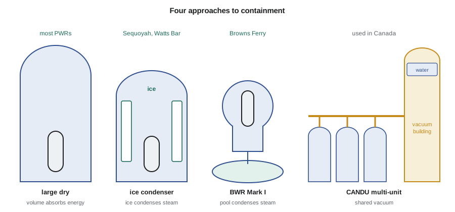
Containments differ more from one design to another than any other major structure. The main approaches are large dry containments, which are big enough to absorb the released energy with a moderate pressure rise; pressure-suppression containments, which condense the steam in a pool of water or in ice; and the multi-unit vacuum building system used at some CANDU stations. All of them must also manage hydrogen, which can be produced by the reaction of hot zirconium cladding with steam in a severe accident.
Large dry containments
Most PWRs worldwide have large dry containments: steel-lined, prestressed or reinforced concrete cylinders with a hemispherical dome, or freestanding steel shells surrounded by a concrete shield building. A typical large dry containment has a free volume of about 50 000 to 80 000 m³ (about 1.8 to 2.8 million ft³) and a design pressure of about 0.4 to 0.5 MPa absolute (about 45 to 60 psig). After a large break, the primary water flashes partly to steam, and the steam and air mix in the containment volume until pressure and temperature reach a peak within seconds to minutes. Containment spray systems and fan coolers then condense the steam and bring the pressure down.
The peak pressure can be estimated with an energy balance. The energy of the released coolant is shared among the steam that remains in the atmosphere, the water that collects on the floor and the air. The final state is the temperature at which the steam partial pressure equals the saturation pressure and the energy balances. The program below makes this estimate for an illustrative large dry containment, ignoring heat absorbed by the structures, which in reality lowers the peak considerably.
# Containment pressure after a large break: energy-balance estimate (illustrative).
# Mix the released primary water with containment air and find the final steam pressure.
V = 70000.0                    # m3 free volume, large dry PWR containment
m_w = 230000.0                 # kg primary water released
h_w = 1450e3                   # J/kg, hot pressurized water
T0 = 30.0
air_kg = V * 1.15              # kg of air at about 100 kPa, 30 C
cp_air = 718.0                 # J/(kg K), constant volume
def sat_p(T):                  # rough saturation pressure in kPa (Antoine-like fit)
    return 0.61094 * 2.718281828 ** (17.625 * T / (T + 243.04)) if T < 100 else \
           101.3 * 2.718281828 ** (5050 * (1/373.15 - 1/(T + 273.15)))
best = None
for Tf10 in range(1000, 1800):
    Tf = Tf10 / 10.0
    p_s = sat_p(Tf) * 1000
    v_g = 0.4615 * (Tf + 273.15) * 1000 / p_s   # ideal-gas steam specific volume
    m_steam = min(m_w, V / v_g)
    m_liq = m_w - m_steam
    E_after = m_steam * (2676e3 + 1.9e3 * (Tf - 100)) + m_liq * 4.2e3 * Tf + air_kg * cp_air * (Tf - T0)
    E_before = m_w * h_w
    if best is None or abs(E_after - E_before) < best[0]:
        best = (abs(E_after - E_before), Tf, p_s, m_steam)
_, Tf, p_s, ms = best
p_air = 100e3 * (Tf + 273.15) / (T0 + 273.15)
print(f"final temperature about {Tf:5.1f} C, steam partial pressure {p_s/1000:5.0f} kPa")
print(f"air partial pressure {p_air/1000:5.0f} kPa, total about {(p_s+p_air)/1000:5.0f} kPa absolute")
print(f"steam in the atmosphere {ms/1000:5.0f} t of {m_w/1000:4.0f} t released")final temperature about 126.3 C, steam partial pressure 247 kPa air partial pressure 132 kPa, total about 379 kPa absolute steam in the atmosphere 94 t of 230 t released
The estimate gives a total pressure near 0.38 MPa absolute, close to the design pressure range of real large dry containments. Detailed codes add the timing of the release, heat transfer to the concrete and steel, spray operation and the energy added by decay heat and by any reaction between zirconium and steam.
Pressure-suppression containments
Pressure-suppression containments use water or ice to condense steam, so the structure can be smaller and designed for a lower peak pressure. In BWR Mark I and Mark II containments, the drywell surrounds the reactor vessel, and vents lead from the drywell into a suppression pool in the wetwell. The Mark III, used in later BWR/6 plants, places the pool in an annulus around the drywell inside a larger containment. Ice condenser containments, used at some PWRs in the United States, store borated ice in baskets in an annular compartment; steam released in the lower compartment forces open inlet doors and condenses as it passes through the ice. The ice melt collects in the sump and is used for long-term recirculation.
Suppression designs are compact and effective for the design basis accident, but their small volume makes hydrogen and long-term pressurization more challenging in a severe accident. At Fukushima Daiichi, the Mark I containments of units 1 to 3 were overpressurized and overheated after cooling was lost, hydrogen leaked into the reactor buildings and exploded, and radioactive material was released. Lessons learned include hardened vent systems capable of operating in severe accident conditions, filtered venting in some countries, and passive hydrogen recombiners.
The CANDU vacuum building
Some CANDU stations in Ontario, including Darlington, use a multi-unit containment system. Each reactor building is connected through a large pressure relief duct to a common vacuum building, kept at a low absolute pressure. If a break pressurizes any reactor building, steam and air flow into the vacuum building and a dousing spray condenses the steam, so the whole containment envelope stays below atmospheric pressure for a period and any leakage is inward. Single-unit CANDU 6 plants use a prestressed concrete containment with a dousing tank in the dome instead.
Worked problem
Free volume and peak pressure
Using the program's result, a release of 230 t of primary water into 70 000 m³ gives a total pressure near 0.38 MPa absolute. Estimate how the steam partial pressure scales if the free volume were halved, keeping everything else the same.
Show solution
- With half the volume, less steam is needed to saturate the space, so the final temperature rises and more of the released water remains as steam per cubic meter.
- The air partial pressure also doubles because the same air occupies half the volume.
- Both effects raise the peak well above the original design pressure; rerunning the program with V = 35 000 m³ shows this.
Answer: A smaller dry containment cannot absorb a large break without suppression, which is why compact designs use pools, ice or a vacuum building.
Isolation, leak testing and hydrogen
Every pipe that penetrates containment has isolation valves, usually one inside and one outside, that close automatically on a containment isolation signal. Electrical penetrations, equipment hatches and personnel airlocks are sealed and tested. Containment leakage is tested periodically by pressurizing the containment and measuring the leakage rate, and individual penetrations and valves are tested more often. Design leakage rates are typically a fraction of a percent of the containment air mass per day at the design pressure.
Hydrogen management is part of every modern containment design. In a severe accident, the reaction of zirconium with steam can produce hundreds of kilograms of hydrogen. Passive autocatalytic recombiners, boxes of catalyst plates that combine hydrogen and oxygen without power, are installed in many containments, including the CANDU fleet and many PWRs. Igniters, which burn hydrogen deliberately at low concentrations before it can accumulate, are used in ice condenser and Mark III containments. Some BWR containments are inerted with nitrogen during operation so that hydrogen cannot burn.
In the United States, containment leakage testing is required by 10 CFR 50 Appendix J. After Fukushima, the NRC ordered reliable hardened vents for BWRs with Mark I and Mark II containments that work under severe accident conditions.
Containment for small modular and advanced reactors
Small reactors change the containment problem. A smaller core holds less energy and decay heat, and integral designs eliminate large pipes. The NuScale design places each module's steel reactor vessel inside its own small steel containment vessel, both submerged in a large pool that acts as the ultimate heat sink. The BWRX-300 uses a compact steel-plate composite containment in a deep below-grade shaft. High-temperature gas reactors, as lesson 9 describes, rely more on the TRISO fuel particles as the main barrier and often use a vented reactor building rather than a pressure-retaining containment. Regulators assess each approach against the same goal: limiting releases under all credible conditions.
Containment structures and external hazards
Containment structures must resist loads from inside and outside. Prestressed concrete containments use steel tendons, tensioned after the concrete has cured, to keep the concrete in compression under internal pressure, with a thin steel liner to provide leak-tightness. The tendons are inspected and their force measured periodically. Reinforced concrete containments rely on heavy reinforcing steel. Steel containments are thick welded steel shells, sometimes surrounded by a concrete shield building that protects against missiles and provides an annulus for filtered ventilation. The structures are designed for the design basis earthquake, for tornado winds and missiles, for external flooding and, for plants licensed after the early 2000s, for the impact of a large commercial aircraft.
Containment also plays a role in normal operation. The containment ventilation system keeps the atmosphere at a suitable temperature and pressure, with filters on exhausts, and access to containment at power is controlled. During outages, the equipment hatch is opened to bring equipment in and out, and procedures ensure it can be closed if needed while fuel is being moved.
Severe accident management in containment
In a severe accident with core damage, the containment must cope with conditions beyond its design basis: higher temperatures, hydrogen and other non-condensable gases, and, if the reactor vessel fails, molten core material on the containment floor reacting with concrete. Severe accident management strategies include flooding the reactor cavity to cool the vessel from outside and retain the molten core in the vessel, controlled venting through filters to prevent containment overpressure failure, and restoring sprays or coolers with portable equipment. Several new designs include a core catcher, a dedicated structure that spreads and cools molten core material.
Isolation and penetrations
Hundreds of pipes, cables and ducts cross the containment boundary. Each pipe that connects to the reactor coolant system or opens to the containment atmosphere has isolation valves, usually one inside and one outside containment, that close automatically on a containment isolation signal such as high containment pressure or low reactor pressure. Lines needed after an accident, such as those for the emergency core cooling and containment spray systems, stay open but form closed systems outside containment. Electrical penetrations are sealed assemblies tested for leak-tightness, and the personnel airlocks have two doors interlocked so that one is always closed. The leak rate testing described in this lesson covers all of these paths, because the containment is only as tight as its weakest penetration.
Isolation is a balance. Closing too many lines could disable systems needed to cool the core; leaving too many open could provide a bypass path for fission products. Designers group lines by function and set isolation signals accordingly.
Common mistakes
MistakeAll reactors use the same type of containment.
InsteadDesigns range from large dry structures to pressure suppression, vacuum buildings and fuel-based retention.
MistakeContainment pressure stays high indefinitely after a break.
InsteadSprays, coolers and condensation bring it down, and CANDU vacuum systems take it below atmospheric.
MistakeHydrogen is only a concern in BWRs.
InsteadAny water-cooled reactor with zirconium cladding can produce hydrogen in a severe accident.
Summary and key terms
- Containment is the last physical barrier and must withstand the design basis loss-of-coolant accident.
- Large dry containments absorb energy with volume; suppression designs condense steam in pools or ice.
- Multi-unit CANDU stations use a shared vacuum building with a dousing tank.
- Isolation valves, leak testing and hydrogen control are part of every containment.
- Small and advanced reactors use compact containments, pools or fuel-based retention.
- Free volume
- The open gas volume inside containment available to absorb released steam.
- Suppression pool
- A pool of water that condenses steam vented from a BWR drywell.
- Ice condenser
- A compartment of borated ice that condenses steam in some PWR containments.
- Vacuum building
- A shared structure held below atmospheric pressure that receives steam from CANDU reactor buildings.
- Passive autocatalytic recombiner
- A device that combines hydrogen and oxygen on a catalyst without power.
- Containment isolation
- Automatic closure of valves in pipes that penetrate containment.
Practice problems
Work each problem on paper first, then reveal the answer to check.
What is the design basis event for containment pressure?
Show answer
Usually the largest loss-of-coolant accident the design must accommodate.
Why can a suppression containment be smaller than a large dry one?
Show answer
Pools or ice condense the steam, limiting the pressure rise.
How does the CANDU vacuum building keep leakage inward?
Show answer
Dousing condenses the steam and the envelope stays below atmospheric pressure for a period.
What do passive autocatalytic recombiners do?
Show answer
Combine hydrogen and oxygen on a catalyst without power.
How does NuScale contain each module?
Show answer
A steel containment vessel around each reactor vessel, submerged in a pool.
Lesson quiz · 5 questions
Score 60% or more to complete this lesson.
Create a free account to save your progress, take quizzes and earn a certificate.