
NUC-360 · Lesson 3 of 12 · 21 min
Boiling water reactors
TVA operates the Browns Ferry boiling water reactors in Alabama and is preparing to build a BWRX-300 at Clinch River. Hana visits Browns Ferry with Dr. Rohan Desai, then studies the BWRX-300 design. "Everything you learned about PWR heat transport is different here," he says. "The coolant boils in the core, the steam goes straight to the turbine, and in the BWRX-300 there are no recirculation pumps at all. The water circulates because the steam in the chimney is lighter than the water around it."
The direct cycle
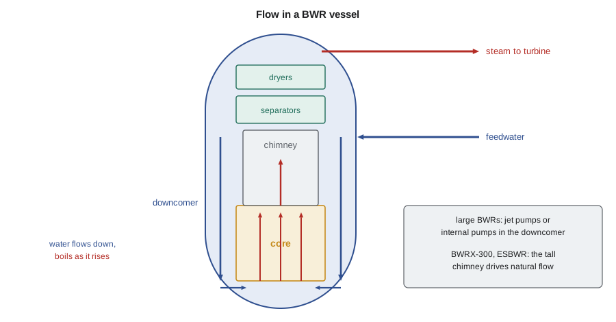
In a boiling water reactor, the coolant boils as it flows up through the core. The vessel operates at about 7 MPa (1 000 psi), where water boils at about 286 °C (547 °F). A steam-water mixture leaves the top of the core, passes through steam separators and dryers in the upper vessel, and dry saturated steam flows out through the main steam lines to the turbine. The separated water returns down the annulus between the core shroud and the vessel wall, mixes with feedwater returning from the condenser, and flows back into the bottom of the core. There are no steam generators and no pressurizer: the vessel itself is the steam generator, and the steam dome above the water is the pressure control.
Removing the steam generators simplifies the plant and lowers the primary pressure, but it brings the turbine into the radiation-controlled area. Coolant passing through the core picks up nitrogen-16, a short-lived activation product of oxygen with a half-life of about 7 seconds, which emits energetic gamma rays. The steam lines and turbine therefore have shielding, and access to the turbine building is restricted while the unit is at power. Because nitrogen-16 decays so quickly, the turbine is accessible soon after shutdown. Small amounts of fission and corrosion products also reach the turbine, so the condenser and feedwater system must be treated as part of the radioactive system.
Core, fuel and control
BWR fuel assemblies are square arrays of zirconium alloy rods, typically 10 × 10 in modern fuel, enclosed in a channel box that keeps the coolant flow in each assembly separate. Groups of four assemblies surround a cruciform control blade, which enters from the bottom of the core and is driven hydraulically. Bottom entry is needed because the steam separators and dryers fill the space above the core. BWRs do not use soluble boron for routine control. Reactivity is controlled by the control blades, by burnable gadolinia in the fuel, and by the core flow rate.
Flow control is one of the distinctive features of large BWRs. Steam voids in the core reduce moderation, because steam is much less dense than water. Raising the core flow sweeps voids out faster, reducing the void fraction, increasing moderation and raising power. Lowering the flow does the opposite. Operators can change power by about 25 percent simply by changing recirculation flow, without moving control blades. The strong negative void coefficient also gives the BWR a self-limiting response: any increase in power creates more steam, which reduces reactivity.
Recirculation and steam quality
Only part of the water entering the core boils on each pass. The ratio of total core flow to steam flow, called the recirculation ratio, is typically between about 5 and 10. The average steam quality at the core exit, the mass fraction of steam, is the inverse of that ratio. The steam flow follows from an energy balance on the vessel: the core power must heat feedwater from its entry temperature and turn it into saturated steam.
In older BWRs, external recirculation pumps drive water through jet pumps inside the vessel annulus. Each jet pump uses a high-velocity driving stream to entrain a larger flow of water from the annulus. The Advanced Boiling Water Reactor, or ABWR, replaced the external loops with ten internal pumps mounted in the bottom of the vessel. The ESBWR and the BWRX-300 eliminate pumps entirely and rely on natural circulation: a tall chimney above the core holds a column of steam-water mixture whose average density is much lower than that of the water in the annulus, and the difference in weight drives the flow.
# BWR: steam quality and core flow for forced and natural circulation (illustrative).
h_f, h_g = 1267e3, 2773e3      # J/kg, saturated water and steam near 7 MPa
h_fg = h_g - h_f
h_fw = 920e3                   # J/kg, feedwater about 215 C
def core(Q, m_core):
    m_steam = Q / (h_g - h_fw)                 # steam flow from overall balance
    x_exit = m_steam / m_core                  # average core exit quality
    return m_steam, x_exit
for name, Q, m in (("Large forced-circulation BWR", 3900e6, 14500.0),
                   ("BWRX-300 natural circulation", 870e6, 3500.0)):
    ms, x = core(Q, m)
    print(f"{name}: steam {ms:6.0f} kg/s, core flow {m:6.0f} kg/s, exit quality {x:5.1%}, "
          f"recirculation ratio {m/ms:4.1f}")
# Natural circulation driving head: density difference over the chimney height
rho_down, g = 740.0, 9.81
for H in (10.0, 20.0):
    for alpha in (0.4, 0.6):
        rho_up = alpha * 36.5 + (1 - alpha) * 740.0
        dp = (rho_down - rho_up) * g * H
print(f"chimney {H:4.0f} m, void fraction {alpha:.1f}: driving head {dp/1000:6.1f} kPa")Large forced-circulation BWR: steam 2105 kg/s, core flow 14500 kg/s, exit quality 14.5%, recirculation ratio 6.9 BWRX-300 natural circulation: steam 470 kg/s, core flow 3500 kg/s, exit quality 13.4%, recirculation ratio 7.5 chimney 10 m, void fraction 0.4: driving head 27.6 kPa chimney 10 m, void fraction 0.6: driving head 41.4 kPa chimney 20 m, void fraction 0.4: driving head 55.2 kPa chimney 20 m, void fraction 0.6: driving head 82.8 kPa
The driving head grows with chimney height and with void fraction. A head of a few tens of kilopascals is small compared with the pressure rise of a pump, so natural circulation designs must have low flow resistance through the core and vessel. That is one reason the BWRX-300 has a tall, slender vessel and a short core.
Worked problem
Exit quality in a natural-circulation BWR
A 870 MW core receives feedwater at h = 920 kJ/kg and produces saturated steam at h_g = 2 773 kJ/kg. Core flow is 3 500 kg/s. Find the steam flow and the core exit quality.
Show solution
- Steam flow: 870 × 10⁶/(2 773 − 920) × 10⁻³ ≈ 470 kg/s.
- Exit quality: 470/3 500 ≈ 0.134, or about 13 percent.
- Recirculation ratio: 3 500/470 ≈ 7.5.
Answer: About one kilogram in seven of the water leaving the core is steam, as the program shows.
Stability
A boiling core has a feedback loop that a PWR lacks. A small increase in power produces more voids, which lower reactivity and power, but the voids take time to travel up the channel, and the change in flow resistance alters the flow. Under some conditions, particularly at high power and low flow, these delays can cause oscillations in power and flow, called density-wave oscillations. Several BWRs experienced such instabilities in the 1980s and 1990s, and operators now avoid a region of the power-flow map and rely on automatic protection that detects oscillations and trips the reactor. Natural circulation designs are analyzed carefully for stability across their whole operating range.
The BWR containment
Because a BWR vessel holds a large volume of water and steam at saturation, a pipe break releases steam quickly. BWRs were designed with compact pressure-suppression containments: a drywell surrounding the vessel and a wetwell, or suppression pool, of water below or around it. Steam released into the drywell is forced through vents into the pool, where it condenses, limiting the pressure rise. The Mark I, Mark II and Mark III designs are successive versions. The Fukushima Daiichi units were BWRs with Mark I containments, and the accident there in 2011 led to new requirements for hardened containment vents, filtered venting in some countries and better hydrogen management.
TVA's Browns Ferry units are BWR/4 plants with Mark I containments. The BWRX-300 planned for Clinch River is the tenth generation of GE Hitachi's boiling water reactor line, producing about 300 MWe from about 870 MW thermal, with natural circulation and passive isolation condensers for decay heat removal.
Advantages and challenges
The direct cycle avoids the cost and maintenance of steam generators, which in PWRs have been a recurring source of tube degradation and replacement projects. The lower pressure reduces the vessel wall thickness. The strong void feedback gives inherent stability against power excursions. On the other side, the turbine and condenser become part of the radiation-controlled plant, maintenance outages involve more radiation protection planning, the vessel is larger for the same power because of the separators and dryers, and stability must be managed. BWRs have run reliably for decades in the United States, Japan, Sweden, Finland, Spain, Switzerland, Taiwan and Mexico.
BWR water chemistry
BWR coolant has no boron or lithium, because the boiling would concentrate them. Instead, the water is kept extremely pure, and radiolysis produces oxygen and hydrogen peroxide in the core. Oxidizing water promotes intergranular stress corrosion cracking of stainless steel and nickel alloy components in the vessel and recirculation piping, which was a widespread problem in the 1970s and 1980s. Utilities responded with hydrogen water chemistry, injecting hydrogen into the feedwater to suppress the oxidizing species, and with noble metal chemistry, depositing small amounts of platinum or similar metals on surfaces to catalyze the recombination of hydrogen and oxygen at low hydrogen injection rates. Zinc injection reduces radiation fields. These measures have greatly reduced cracking in the fleet.
Startup, operation and the power-flow map
A BWR starts up by withdrawing control blades to reach criticality at low temperature, then heating the coolant with nuclear heat and drawing steam to the condenser through the turbine bypass valves until the turbine can be synchronized. In forced-circulation plants, power is then raised along a path on the power-flow map, a chart of thermal power against core flow, using a combination of blade withdrawal and recirculation flow increases while staying outside the region where instabilities are possible. Fuel performance limits, such as the minimum critical power ratio described in NUC-330, are checked continuously by the plant's core monitoring system, which combines in-core detector readings with a core simulator.
A natural circulation BWR has a simpler power-flow relationship: the core flow rises with power because more voids in the chimney give more driving head. Power is controlled mainly by the control blades and by the feedwater temperature, which changes the subcooling of the water entering the core. Designers must show stable operation across the whole range from startup to full power.
The BWR fleet
General Electric developed the BWR from the 1950s, through a series of designs from the BWR/1 to the BWR/6, and later the ABWR with Toshiba and Hitachi and the ESBWR. The ABWR was the first generation III reactor to operate, in Japan in 1996. ASEA-Atom, later Westinghouse Sweden, developed BWRs in Sweden and Finland. The BWRX-300 is a simplified, smaller descendant of the ESBWR design.
Refueling and the reactor building
Refueling a BWR also requires the reactor to be shut down and the vessel opened. The steam dryer and steam separator assembly are lifted from the vessel and set aside under water in an equipment pool, because they are radioactive from contact with the steam. Fuel is then moved through a flooded cavity to the spent fuel pool, which in most BWR designs sits high in the reactor building next to the vessel. Control blades and in-core detectors can be replaced during the same outage. Because the turbine is exposed to radioactive steam, the turbine hall in a BWR has shielding and access controls that a PWR turbine hall does not need, and turbine maintenance during outages is planned with radiation exposure in mind. Most of the dose comes from nitrogen-16 when the plant is running, which decays within minutes after shutdown, so outage work on the turbine is far less restricted than work near the reactor.
The overall result is a plant with fewer major components than a PWR, no steam generators to inspect or replace, and a simpler primary system, balanced against a larger reactor vessel, a radioactive turbine and a more complex core physics problem.
Common mistakes
MistakeA BWR has steam generators like a PWR.
InsteadThe vessel itself produces steam; there are no steam generators.
MistakeBWR control rods enter from the top.
InsteadThey enter from the bottom, because separators and dryers occupy the space above the core.
MistakeRaising recirculation flow lowers BWR power.
InsteadHigher flow sweeps voids out, increases moderation and raises power.
Summary and key terms
- A BWR boils coolant in the core at about 7 MPa and sends steam directly to the turbine.
- Steam separators and dryers in the upper vessel remove moisture.
- Core flow changes power by changing the void fraction.
- Natural circulation BWRs use a chimney instead of recirculation pumps.
- Pressure-suppression containments condense released steam in a pool.
- Recirculation ratio
- The ratio of total core flow to steam flow in a BWR.
- Steam quality
- The mass fraction of steam in a steam-water mixture.
- Jet pump
- A device that uses a high-velocity driving stream to entrain flow in a BWR annulus.
- Chimney
- A tall open region above a natural circulation BWR core that provides buoyancy head.
- Suppression pool
- A pool of water in a BWR containment that condenses released steam.
- Nitrogen-16
- A short-lived activation product in BWR steam that makes the turbine a radiation area at power.
Practice problems
Work each problem on paper first, then reveal the answer to check.
Why is the turbine in a BWR a radiation area at power?
Show answer
Nitrogen-16 in the steam emits energetic gamma rays.
How does a BWR change power without moving control blades?
Show answer
By changing core flow, which changes the void fraction and moderation.
What drives the flow in the BWRX-300?
Show answer
The density difference between the steam-water mixture in the chimney and the water in the annulus.
A core makes 450 kg/s of steam with 3 600 kg/s of core flow. What is the exit quality?
Show answer
About 12.5 percent.
What is the purpose of the suppression pool?
Show answer
To condense steam released into the drywell and limit containment pressure.
Lesson quiz · 5 questions
Score 60% or more to complete this lesson.
Create a free account to save your progress, take quizzes and earn a certificate.