
NUC-360 · Lesson 2 of 12 · 21 min
Pressurized water reactors
Teodora sends Hana to the full-scope simulator at the training center, where an instructor is running a TVA crew through a scenario on a four-loop pressurized water reactor. Hana watches the reactor operator hold pressurizer level steady while the turbine load is reduced. "Most of what you will do for TVA starts here," Teodora says. "Learn the primary circuit until you can draw it from memory."
The idea of the PWR
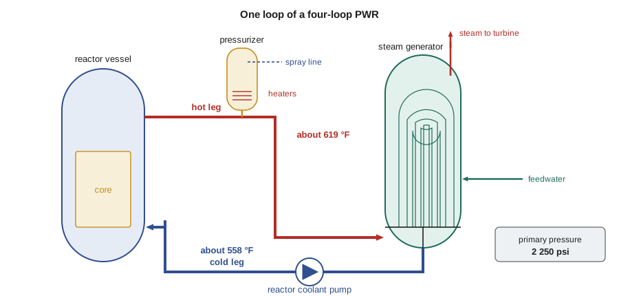
A pressurized water reactor keeps its coolant liquid by holding it at high pressure, about 15.5 MPa (2 250 psi). At that pressure water boils at about 345 °C (653 °F), so the coolant can leave the core at about 325 °C (617 °F) with a comfortable margin to bulk boiling. The hot coolant flows to steam generators, where it boils water in a separate secondary circuit at a lower pressure, about 6 to 7 MPa. The primary coolant then returns, through reactor coolant pumps, to the reactor vessel. Because the primary coolant never leaves containment and never boils in bulk, the steam going to the turbine is not radioactive under normal conditions.
The PWR was developed in the United States for naval propulsion and adapted for electricity production in the late 1950s. Its compact core, high power density and use of ordinary water made it attractive for large-scale deployment, and it became the dominant reactor type worldwide. Westinghouse, Combustion Engineering and Babcock and Wilcox built PWRs in the United States; Framatome in France; and versions were developed in Japan, South Korea, Russia and China. Russian PWRs are known as VVERs.
The core and fuel
A large PWR core holds about 150 to 250 fuel assemblies. A typical Westinghouse four-loop core has 193 assemblies, each a 17 × 17 square array of positions holding 264 fuel rods and 25 guide tubes for control rods and instruments. The fuel rods are zirconium alloy tubes about 9.5 mm (0.374 in) in diameter and about 4 m (12 ft) of active length, filled with uranium dioxide pellets enriched to about 3 to 5 percent uranium-235. The core is about 3.4 m (11 ft) across and about 3.7 m (12 ft) high. It is refueled in batches, typically a third of the core every 18 months, as covered in NUC-350.
Reactivity is controlled in three ways. Control rod clusters, inserted from the top through the vessel head, provide fast shutdown and power shaping. Boric acid dissolved in the coolant compensates for slow changes such as fuel burnup and xenon; the boron concentration is high at the start of a cycle and is diluted toward zero by the end. Burnable absorbers in some fuel rods hold down excess reactivity early in the cycle. The negative moderator temperature coefficient means that the core naturally resists power increases: if the coolant heats up, it expands, moderation falls and reactivity drops.
The reactor vessel and internals
The reactor pressure vessel is a thick-walled cylinder of low-alloy steel lined with stainless steel cladding, about 4.4 m (14.4 ft) in inside diameter and over 12 m (40 ft) tall, with walls about 200 to 250 mm (8 to 10 in) thick. Coolant enters through inlet nozzles, flows down the annulus between the vessel wall and the core barrel, turns at the bottom and flows up through the core. It leaves through outlet nozzles at the same elevation as the inlets. The lower plenum and the core support structures distribute the flow evenly. The upper head carries the control rod drive mechanisms, which hold the rods with electromagnets so that cutting power to the magnets drops the rods by gravity. As NUC-340 described, the vessel steel near the core is monitored for irradiation embrittlement throughout the life of the plant.
Coolant flow and the temperature rise
The coolant must carry the full thermal power out of the core with a temperature rise that keeps the hot leg well below boiling. A mass balance gives the flow needed:
For a 3 411 MW core with a temperature rise of about 34 K, the flow is close to 18 metric tons per second, shared among four loops. The reactor coolant pumps are large vertical centrifugal pumps driven by motors of several megawatts each. They have a heavy flywheel so that if power to the pumps is lost, they coast down slowly over a minute or more, carrying the core through the transition to natural circulation. Natural circulation, driven by the density difference between hot and cold legs, can remove decay heat once the reactor has tripped.
# PWR primary loop: flow, temperature rise and pressurizer behavior (illustrative).
Q = 3411e6                     # W, core thermal power
loops = 4
T_cold, T_hot = 292.0, 326.0   # deg C, about 15.5 MPa
cp = 5600.0                    # J/(kg K), average for water in this range
m_core = Q / (cp * (T_hot - T_cold))
print(f"core mass flow {m_core/1000:6.2f} t/s, per loop {m_core/loops/1000:5.2f} t/s")
rho_cold = 745.0               # kg/m3 near 292 C, 15.5 MPa
print(f"volume flow per loop about {m_core/loops/rho_cold:5.2f} m3/s")
# Pressurizer: a coolant swell from heating the primary by 1 K
V_primary = 300.0              # m3, rough primary water volume
beta = 3.0e-3                  # 1/K, volumetric expansion of hot water
dV = V_primary * beta * 1.0
print(f"a 1 K rise in average temperature pushes about {dV:4.2f} m3 into the pressurizer")
# Average temperature program: Tavg rises from no load to full power
for load in (0.0, 0.5, 1.0):
    tavg = 291.7 + (309.0 - 291.7) * load
print(f"load {load:4.0%}: programd average temperature {tavg:5.1f} C")core mass flow 17.91 t/s, per loop 4.48 t/s volume flow per loop about 6.01 m3/s a 1 K rise in average temperature pushes about 0.90 m3 into the pressurizer load 0%: programd average temperature 291.7 C load 50%: programd average temperature 300.4 C load 100%: programd average temperature 309.0 C
The pressurizer
The pressurizer is a vertical vessel connected to one hot leg, partly full of water and partly full of steam at saturation. It controls primary pressure and accommodates changes in coolant volume. Electric heaters near the bottom boil water to raise pressure; a spray line from the cold leg condenses steam to lower it. When the primary coolant heats up and expands, water surges into the pressurizer, compressing the steam space and raising pressure until the spray acts. When the coolant cools and contracts, water flows out and the heaters act. Power-operated relief valves and spring-loaded safety valves on top of the pressurizer protect against overpressure, discharging to a quench tank inside containment.
The pressurizer level is programd to vary with power, because the average coolant temperature rises with load. As the program output shows, a single kelvin of average temperature change moves almost a cubic meter of water into or out of the pressurizer. The chemical and volume control system adds or removes water to keep level on program and adjusts boron concentration. The relief valve on a pressurizer played a central role in the Three Mile Island accident in 1979, when a valve stuck open and operators, misled by pressurizer level, reduced the emergency injection flow.
Worked problem
Coolant flow per loop
A 3 411 MW core has a cold-leg temperature of 292 °C and hot-leg temperature of 326 °C. With c_p ≈ 5 600 J/kg·K, what is the flow per loop for a four-loop plant?
Show solution
- Total flow: ṁ = 3.411 × 10⁹/(5 600 × 34) ≈ 17 900 kg/s.
- Per loop: 17 900/4 ≈ 4 480 kg/s.
- At a density of about 745 kg/m³, that is about 6 m³/s per loop (about 95 000 US gal/min).
Answer: Each reactor coolant pump moves about 4.5 metric tons of water per second, as the program found.
Supporting systems
Around the primary circuit sits a set of supporting systems. The chemical and volume control system maintains coolant inventory, purity and boron concentration, and supplies seal water to the reactor coolant pumps. The residual heat removal system cools the reactor during shutdown, once pressure and temperature have fallen enough. The component cooling water system cools the pump seals, heat exchangers and other components, rejecting heat to the service water system. The emergency core cooling systems, covered in lesson 6, inject borated water into the primary circuit if a pipe breaks. The containment, covered in lesson 7, surrounds the whole primary circuit.
The PWR fleet in the United States includes Westinghouse two-, three- and four-loop plants, Combustion Engineering two-loop plants with large steam generators, and Babcock and Wilcox plants with once-through steam generators. The newest units, Vogtle 3 and 4 in Georgia, are Westinghouse AP1000 plants with passive safety systems, which lesson 6 describes.
Advanced PWR designs
Later PWR designs build on the same principles with changes to safety systems and construction. The Westinghouse AP1000 uses passive safety systems that rely on gravity, natural circulation and compressed gas rather than pumps and emergency diesel generators, and it has two loops with very large steam generators and canned-motor pumps mounted directly on the steam generator. The European Pressurized Reactor, or EPR, is a large four-loop design with four independent trains of active safety systems and a core catcher beneath the vessel. The Korean APR1400 and the Chinese Hualong One are other evolutionary designs. Small modular PWRs, such as NuScale and others described in lesson 8, shrink the plant and integrate the steam generators inside the reactor vessel.
Normal operation and startup
Starting a PWR from cold shutdown is a long, carefully sequenced process. The primary system is filled and vented, and the reactor coolant pumps are started to circulate and heat the coolant by pump heat. The pressurizer heaters draw a steam bubble, and the plant is brought up in temperature and pressure to hot standby, close to normal operating temperature with the reactor still subcritical. Boron is diluted to the estimated critical concentration, and control rods are withdrawn in sequence until the reactor becomes critical. The operators then raise power slowly, with careful attention to the flux distribution, to the point where the turbine can be synchronized to the grid, and then raise power to full load over hours. Each stage has limits on heat-up rate and on pressure at a given temperature, set to protect the reactor vessel against brittle fracture, as NUC-340 described.
At power, the PWR follows the turbine. If the turbine takes more steam, the steam generators cool the primary coolant slightly, the negative moderator temperature coefficient adds reactivity and power rises to match the new demand, while the rod control system restores the programd average temperature. This load-following behavior is a direct consequence of the reactor's negative temperature feedback, and it makes the PWR stable and forgiving in normal operation.
Primary coolant chemistry
The primary coolant is high-purity water with controlled additions. Boric acid controls reactivity, and lithium hydroxide raises the pH to reduce corrosion and the transport of corrosion products into the core, where they would become activated and raise radiation fields around the plant. Dissolved hydrogen suppresses the formation of oxygen and hydrogen peroxide by radiolysis. Many plants add small amounts of zinc to reduce radiation fields and stress corrosion cracking. Chemistry engineers adjust lithium as boron is diluted through the cycle to keep pH in its target band, and they monitor activity in the coolant to detect any leaking fuel rods.
Shutdown and cooldown
Shutting a PWR down for a refueling outage reverses the startup. Power is reduced, the turbine is taken off line, and the control rods are inserted. The operators borate the coolant to the cold shutdown concentration so that the core stays subcritical as it cools and the moderator temperature coefficient adds reactivity. Decay heat is removed first through the steam generators, dumping steam to the condenser, and then, below about 180 °C and 3 MPa, by the residual heat removal system, which takes water from a hot leg, passes it through heat exchangers and returns it to the cold legs. The cooldown rate is limited, typically to about 55 K per hour, to keep thermal stresses in the vessel and piping within their limits. Once the system is cold and depressurized, the vessel head is removed, the refueling cavity above the vessel is flooded with borated water, and fuel is moved under water to the spent fuel pool.
The period with the reactor coolant system partly drained, used for work on the steam generators or pumps, needs particular care. With the water level near the middle of the hot leg pipes, a small error in level can let the residual heat removal pumps draw in air and lose suction. Plants use dedicated level instruments and procedures for this mid-loop condition.
Common mistakes
MistakeThe PWR primary coolant boils in the core.
InsteadIt is kept liquid by high pressure; only the secondary water boils, in the steam generators.
MistakeThe pressurizer holds pressure with a pump.
InsteadIt uses electric heaters and cold-leg spray on a saturated steam bubble.
MistakeSoluble boron is used for fast shutdown.
InsteadControl rods provide fast shutdown; boron compensates for slow reactivity changes.
Summary and key terms
- A PWR keeps its coolant liquid at about 15.5 MPa and boils secondary water in steam generators.
- A large core has about 193 assemblies of 17 × 17 rods of enriched UO₂.
- Control rods, soluble boron and burnable absorbers control reactivity.
- The pressurizer controls pressure with heaters, spray and a steam bubble.
- Reactor coolant pumps move about 4 to 5 metric tons per second per loop in a large plant.
- Hot leg
- The pipe carrying heated coolant from the reactor vessel to a steam generator.
- Cold leg
- The pipe returning coolant from a steam generator through a pump to the vessel.
- Pressurizer
- A vessel holding a saturated steam bubble that controls primary pressure.
- Chemical and volume control system
- The system that adjusts coolant inventory, chemistry and boron concentration.
- Moderator temperature coefficient
- The change in reactivity per degree of coolant temperature change; negative in a PWR.
- VVER
- The Russian family of pressurized water reactors.
Practice problems
Work each problem on paper first, then reveal the answer to check.
Why does the PWR primary coolant not boil at 325 °C?
Show answer
At 15.5 MPa the saturation temperature is about 345 °C.
What do the pressurizer heaters and spray do?
Show answer
Heaters boil water to raise pressure; spray condenses steam to lower it.
Why do reactor coolant pumps have flywheels?
Show answer
To coast down slowly after a power loss, easing the transition to natural circulation.
How is reactivity compensated over a fuel cycle in a PWR?
Show answer
Mainly by diluting soluble boron as the fuel burns up.
What feature of the AP1000 distinguishes it from earlier PWRs?
Show answer
Passive safety systems that work without pumps or diesel generators.
Lesson quiz · 5 questions
Score 60% or more to complete this lesson.
Create a free account to save your progress, take quizzes and earn a certificate.