
NUC-350 · Lesson 8 of 12 · 20 min
Batch refueling in LWRs
Hana's first reload outage is planned eleven months out. The reload package on her screen lists 72 fresh assemblies at a little over 4 percent enrichment, 121 burned assemblies to be shuffled and 72 to be discharged to the spent fuel pool. "Once every eighteen months we open the vessel and rebuild about a third of the core," Teodora says. "Everything we do between outages is about getting the most out of that one decision."
Why light-water reactors refuel in batches
A pressurized or boiling water reactor holds its core inside a single large pressure vessel. The vessel head must be removed to reach the fuel, which can only be done with the reactor shut down, cooled and depressurized, and the refueling cavity flooded with borated water. Refueling is therefore done in batches during planned outages. Enriched uranium gives each fresh assembly far more reactivity than needed, so the core can carry enough excess reactivity at the start of a cycle to run for a year and a half or two years. Burnable absorbers and soluble boron hold that excess down.
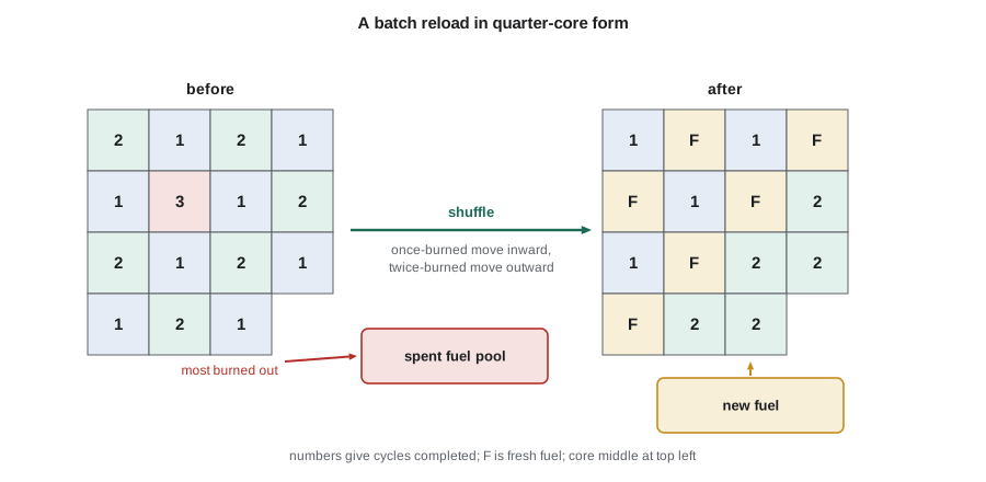
During an outage, the refueling machine moves assemblies one at a time under water. The most burned assemblies are discharged to the spent fuel pool, the remaining burned assemblies are shuffled to new positions, often rotated, and fresh assemblies are loaded. The new arrangement is the loading pattern designed for the next cycle, as lesson 7 described. Modern outages take roughly three to five weeks, of which the fuel movement itself is a few days.
The linear reactivity model
A simple model explains how batch size and discharge burnup are related. Over most of its life, the k_inf of a light-water assembly falls roughly linearly with burnup: k(B) = k₀ − aB. In a core with n batches, each batch spends n cycles in the core. At the end of a cycle, the core is just critical when the average k of all batches, less a leakage allowance, equals one. Solving this condition gives the discharge burnup:
where B₁ is the burnup reachable if the whole core were loaded and discharged at once. A two-batch core reaches 1.33 times B₁, a three-batch core 1.5 times and a four-batch core 1.6 times. More batches mean higher discharge burnup and better uranium use, but each cycle produces less energy, so cycles are shorter or need more enriched fuel. The program below works through the model and estimates cycle lengths for a 193-assembly core.
# Batch refueling in a light water reactor: the linear reactivity model.
# k_inf of an assembly falls roughly linearly with burnup: k(B) = k0 - a*B.
# With n batches, the core is critical when the average k over the batches,
# less a leakage allowance, equals 1. Values are illustrative.
k0, a, leak = 1.30, 0.0070, 0.04       # a in delta-k per MWd/kgU
B1 = (k0 - 1 - leak) / a                # single-batch burnup
print(f"single-batch discharge burnup B1 = {B1:.1f} MWd/kgU")
for n in (1, 2, 3, 4):
    Bd = 2 * n / (n + 1) * B1           # discharge burnup with n batches
    print(f"  {n} batch(es): discharge burnup {Bd:5.1f} MWd/kgU, cycle burnup {Bd / n:5.1f} MWd/kgU, "
          f"fraction of core replaced each cycle {1/n:.2f}")
# Cycle length from cycle burnup for a 193-assembly core
assemblies, kgU_per_assembly = 193, 460.0
power_MWt = 3459.0
core_kgU = assemblies * kgU_per_assembly
for n in (2.2, 2.5, 3.0):
    Bc = 2 * n / (n + 1) * B1 / n
    efpd = Bc * core_kgU / power_MWt
    print(f"with about {n} batches the cycle lasts about {efpd:.0f} effective full-power days "
f"({efpd / 30.4:.1f} months at full power)")single-batch discharge burnup B1 = 37.1 MWd/kgU 1 batch(es): discharge burnup 37.1 MWd/kgU, cycle burnup 37.1 MWd/kgU, fraction of core replaced each cycle 1.00 2 batch(es): discharge burnup 49.5 MWd/kgU, cycle burnup 24.8 MWd/kgU, fraction of core replaced each cycle 0.50 3 batch(es): discharge burnup 55.7 MWd/kgU, cycle burnup 18.6 MWd/kgU, fraction of core replaced each cycle 0.33 4 batch(es): discharge burnup 59.4 MWd/kgU, cycle burnup 14.9 MWd/kgU, fraction of core replaced each cycle 0.25 with about 2.2 batches the cycle lasts about 596 effective full-power days (19.6 months at full power) with about 2.5 batches the cycle lasts about 545 effective full-power days (17.9 months at full power) with about 3.0 batches the cycle lasts about 477 effective full-power days (15.7 months at full power)
With these illustrative numbers, replacing a little less than half of the core each cycle gives about 20 months of full-power operation, and replacing a third gives about 16 months. Real 18-month cycles typically replace roughly 40 percent of the core, with fresh fuel of about 4 to 5 percent enrichment, and reach discharge burnups near 50 MWd/kgU. The linear model is too simple for design, but it explains the trade-off every utility faces between cycle length, batch size, enrichment and discharge burnup.
Worked problem
Discharge burnup and batches
An assembly design has k₀ = 1.30, a = 0.0070 per MWd/kgU and a leakage allowance of 0.04. Find the discharge burnup for 2.5 batches.
Show solution
- B₁ = (1.30 − 1 − 0.04)/0.0070 = 37.1 MWd/kgU.
- B_d = 2 × 2.5/3.5 × 37.1 = 1.429 × 37.1 = 53.0 MWd/kgU.
- Cycle burnup = B_d/n = 53.0/2.5 = 21.2 MWd/kgU.
Answer: About 53 MWd/kgU at discharge and 21 MWd/kgU per cycle, consistent with the program output and with typical 18-month PWR operation.
Cycle length and the operating plan
Most U.S. pressurized water reactors run on 18-month cycles, and some on 24-month cycles. TVA's units, like most, plan their outages for spring and autumn, when demand is lower. The cycle length in effective full-power days is set by the utility's plan, and the reload must provide enough reactivity to reach it with margin, plus some ability to stretch the cycle by coasting down if the outage is delayed. Coastdown means letting power fall gradually at the end of the cycle as the moderator temperature drops, using the negative moderator temperature coefficient to gain reactivity. It is a common way to extend a cycle by a few weeks.
The planned cycle length drives the enrichment and number of fresh assemblies. Longer cycles need either more fresh assemblies, which raises fuel cost per unit energy because burned fuel is discharged at lower burnup, or higher enrichment, which is limited by the 5 percent enrichment licensed for most fuel facilities and by burnup limits on the fuel. Industry and regulators are now working on fuel enriched somewhat above 5 percent, still within the low-enriched range, to support higher burnups and longer cycles.
Burnup, discharge and spent fuel
Each reload discharges a batch of fuel that has reached the end of its useful reactivity. In the United States, discharged fuel goes first to the spent fuel pool for several years of cooling, then to dry cask storage on the plant site. Core designers keep track of each discharged assembly's burnup, initial enrichment and cooling time, because these determine its decay heat, radiation source terms and criticality characteristics in storage. Credit for burnup in storage criticality analyzes, called burnup credit, depends on the depletion calculations described in lesson 4.
The BWRX-300 and other designs
Boiling water reactors also refuel in batches, but their design is shaped by void fraction and control blades. The BWRX-300 planned at Clinch River is a small, natural-circulation boiling water reactor with a core much smaller than TVA's large pressurized water reactors. Its fuel management is designed around cycles of roughly one to two years, with gadolinia for reactivity hold-down and control blades that move during the cycle in a planned sequence. The same principles apply: a linear-reactivity balance sets discharge burnup, and loading patterns control peaking and margins.
What happens during a refueling outage
A refueling outage follows a carefully planned sequence. The reactor is shut down and cooled, the primary system is depressurized and the boron concentration is raised to the refueling value, chosen so that the core stays well subcritical with all control rods removed. The vessel head is lifted off and the refueling cavity above the vessel is flooded with borated water. The refueling machine then moves assemblies one at a time between the core, the transfer system and the spent fuel pool. Throughout fuel movement, source range detectors monitor the neutron count rate, and the core physics engineers check after defined steps that the count rate behaves as predicted, confirming that the core remains subcritical as the new arrangement is built.
| Outage step | Purpose | Physics check |
|---|---|---|
| Shutdown, cooldown and boration to refueling concentration | safe subcritical state with rods removed | shutdown margin at refueling boron |
| Head removal and cavity flooding | access to the core under water | boron concentration verified |
| Core offload or shuffle | move burned fuel and remove discharged fuel | source range count rates monitored |
| Fresh fuel loading | build the new loading pattern | inverse count rate checks as fuel is added |
| Core verification | confirm every assembly is in its planned position | video or serial number check |
| Head replacement and start-up | return to power | start-up physics tests |
The core verification step deserves emphasis. A single assembly loaded in the wrong position can change the power distribution enough to exceed a peaking limit. After loading, the core is therefore checked assembly by assembly against the loading plan, and the start-up physics tests, including flux maps at low power, give a further check that the core matches its design. Lesson 12 returns to these tests as the last step of a reload design.
Planning for each refueling outage begins years in advance. The utility decides the target cycle length based on its grid commitments, the outage schedule and the fuel budget, and the reload design is developed to meet that target. The fuel vendor needs the enrichments and burnable absorber designs about a year before the outage so that the uranium can be ordered and fabricated. Throughout this period, the design is updated as the current cycle runs, because the actual burnup at the end of the cycle depends on how the plant has operated.
The end of cycle itself can be stretched. When the boron concentration reaches its lowest practical value, the reactor can continue for a while in coastdown, with power slowly decreasing as reactivity falls. Coastdown extends the cycle energy at the cost of lower output near the end. Plants may also use a slight reduction in coolant temperature to gain reactivity through the negative moderator temperature coefficient, within the limits set by the safety analysis.
Mid-cycle changes are also possible. If an assembly is found to be leaking, it may be replaced during a short outage, and the loading pattern adjusted to keep peaking within limits. Such changes require a new reload safety evaluation for the remaining cycle.
Fuel handling during the outage is itself carefully controlled. Every move in the shuffle sequence is listed in advance, and each assembly's identity and location are verified by camera before and after the move. Core monitoring instruments track the neutron count rate throughout, so that any unexpected rise would stop the work. When the last assembly is in place, a final verification of the whole core map confirms that the loading matches the design before the vessel head is replaced.
Discharged assemblies go to the spent fuel pool, where their burnup and decay heat are recorded. After several years of cooling, they can be transferred to dry cask storage. The records kept for each assembly, from its enrichment and burnable absorbers to its burnup history, support these later steps and the criticality safety analyzes of the pool and casks.
Hana ends her first reload study with a short summary for Teodora: batch size, enrichment, predicted cycle length and discharge burnup, and the main uncertainties. The numbers will change as the current cycle runs, but the method will stay the same.
Common mistakes
MistakeA larger batch fraction always gives better fuel economy.
InsteadLarger batches allow longer cycles but lower discharge burnup, so more uranium is used per unit energy.
MistakeCycle length depends only on the number of fresh assemblies.
InsteadIt also depends on enrichment, burnable absorbers, the loading pattern and coastdown.
MistakeFuel is discharged when it has burned all of its uranium-235.
InsteadIt is discharged when the batch can no longer keep the core critical, with plenty of uranium-235 and plutonium remaining.
Summary and key terms
- Light-water reactors refuel in batches during planned outages because the fuel is inside a single pressure vessel.
- Each outage discharges the most burned fuel, shuffles the rest and loads fresh fuel.
- The linear reactivity model gives discharge burnup as 2n/(n+1) times the single-batch burnup.
- Cycle length, batch fraction, enrichment and discharge burnup trade against each other.
- Coastdown at the end of a cycle uses the moderator temperature coefficient to extend operation.
- Batch
- The group of fresh assemblies loaded together at one refueling outage.
- Batch fraction
- The fraction of the core replaced at each refueling.
- Linear reactivity model
- A model in which assembly reactivity falls linearly with burnup.
- Effective full-power day
- The energy produced by the core at full power for one day.
- Coastdown
- Gradual power reduction at end of cycle that extends operation using reactivity feedback.
- Burnup credit
- Taking credit for the reduced reactivity of burned fuel in storage criticality analyzes.
Practice problems
Work each problem on paper first, then reveal the answer to check.
Why can a PWR not refuel on power?
Show answer
Its fuel is inside a single pressure vessel whose head must be removed with the reactor shut down and depressurized.
What discharge burnup multiple does a three-batch core reach in the linear model?
Show answer
1.5 times the single-batch burnup.
In the example, what is the cycle burnup for 2.5 batches?
Show answer
About 21 MWd/kgU.
What is coastdown?
Show answer
Letting power fall at end of cycle so the negative moderator temperature coefficient adds reactivity and extends the cycle.
Why does a longer cycle tend to raise fuel cost per unit energy?
Show answer
It needs more fresh assemblies or higher enrichment, and burned fuel is discharged at lower burnup.
Lesson quiz · 5 questions
Score 60% or more to complete this lesson.
Create a free account to save your progress, take quizzes and earn a certificate.