
NUC-350 · Lesson 12 of 12 · 19 min
Fuel management project
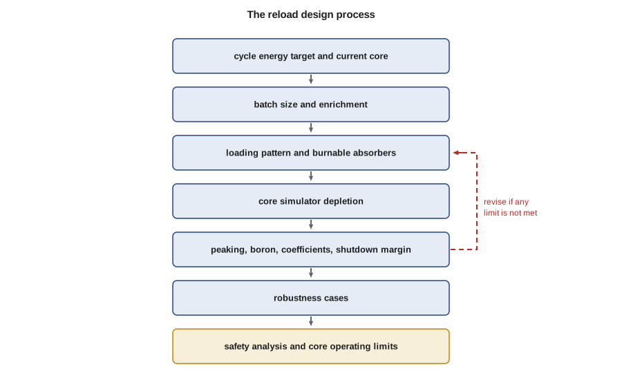
For her final assignment in the core physics group, Teodora hands Hana a real problem in simplified form: prepare the first-pass reload design for the next cycle of one of TVA's pressurized water reactors, write the justification and present it at the design review. "Everything you have learned this year goes into this," Teodora says. "Burnup, enrichment, burnable absorbers, the loading pattern, boron, shutdown margin, the codes and their uncertainties. The answer must be safe first, economical second and robust if the outage moves."
The project brief
The utility's plan calls for a cycle of about 510 effective full-power days, roughly 18 months with typical capacity factor and outage time. The current core will be discharged in eleven months; its projected end-of-cycle burnups are known. The reload design must meet these requirements:
| Requirement | Why it matters | How it is checked |
|---|---|---|
| Cycle energy | the unit must reach the planned outage with margin | core simulator depletion to end of cycle at the required boron |
| Peaking factors F_q and F_ΔH | protect fuel and margin to departure from nucleate boiling | predicted peaks with uncertainty allowance against limits |
| Shutdown margin | safe shutdown with the most reactive rod stuck | calculated at the most reactive point in the cycle |
| Moderator temperature coefficient | must meet the technical specification limit, especially at the start of the cycle | calculated at hot zero and full power |
| Discharge burnup and fuel limits | stay within licensed burnup limits for the fuel design | assembly and rod burnups at discharge |
| Fuel cost | number of fresh assemblies and enrichment | cost per unit energy |
Step 1: sizing the reload
Hana starts with the linear reactivity model of lesson 8 to size the fresh batch. For each candidate number of fresh assemblies, she finds the lowest enrichment that gives the target cycle length, and the resulting discharge burnup. Fewer fresh assemblies at higher enrichment give higher discharge burnup and lower fuel cost per unit energy, as long as the burnup limit and the peaking limits can be met.
# Fuel management project (PWR-like): size the reload for an 18-month cycle.
# Linear reactivity model: find the feed batch fraction and enrichment that give the
# target cycle length, then check the peaking factor limit. Values are illustrative.
target_efpd = 510
power_MWt, assemblies, kgU = 3459.0, 193, 460.0
leak, a = 0.04, 0.0070               # leakage allowance, reactivity slope per MWd/kgU
def k0_for(enrich):                  # fresh k_inf rises with enrichment (fit)
    return 1.05 + 0.058 * enrich
def cycle_efpd(n_batches, enrich):
    B1 = (k0_for(enrich) - 1 - leak) / a
    Bc = 2 * B1 / (n_batches + 1)    # cycle burnup
    return Bc * assemblies * kgU / power_MWt, 2 * n_batches / (n_batches + 1) * B1
print("feed assemblies | enrichment % | cycle EFPD | discharge burnup")
best = None
for feed in (72, 80, 84, 88):
    n = assemblies / feed
    for e10 in range(30, 50):
        e = e10 / 10
        efpd, bd = cycle_efpd(n, e)
        if efpd >= target_efpd:
            print(f"{feed:15d} | {e:12.1f} | {efpd:10.0f} | {bd:16.1f}")
            if best is None and bd <= 60: best = (feed, e, efpd, bd)
            break
fq_pred, fq_limit = 2.38, 2.50
feed, e, efpd, bd = best
print(f"chosen reload: {feed} fresh assemblies at {e:.1f} % for {efpd:.0f} EFPD; "
f"predicted peak Fq {fq_pred} against a limit of {fq_limit} -> margin {100*(fq_limit-fq_pred)/fq_limit:.1f} %")feed assemblies | enrichment % | cycle EFPD | discharge burnup
72 | 4.3 | 517 | 54.0
80 | 4.0 | 520 | 48.9
84 | 3.8 | 512 | 45.9
88 | 3.7 | 516 | 44.1
chosen reload: 72 fresh assemblies at 4.3 % for 517 EFPD; predicted peak Fq 2.38 against a limit of 2.5 -> margin 4.8 %The smallest batch, 72 fresh assemblies at 4.3 percent, reaches the cycle target with a discharge burnup near 54 MWd/kgU, within typical licensed limits. Larger batches allow lower enrichment but discharge fuel at lower burnup. Hana selects 72 assemblies at 4.3 percent for the first-pass design, subject to the loading pattern meeting the peaking limits.
Step 2: the loading pattern and burnable absorbers
With the batch chosen, Hana builds a low-leakage pattern in quarter-core symmetry. Twice-burned assemblies from the current core go to the periphery; once-burned assemblies are mixed with the fresh assemblies in the interior, with no two fresh assemblies sharing a face. She assigns burnable absorbers: most fresh assemblies get integral fuel burnable absorber rods, and the few in the highest-worth positions also get gadolinia rods. She then runs the core simulator through the cycle, adjusting the number of absorber rods until the peak F_ΔH stays below its limit throughout and the beginning-of-cycle critical boron gives an acceptable moderator temperature coefficient.
Worked problem
Peaking margin
The predicted maximum F_q in the cycle is 2.38. The methodology's uncertainty allowance is 5 percent and the limit is 2.50. Is the design acceptable?
Show solution
- F_q with allowance: 2.38 × 1.05 = 2.50.
- Compare with the limit: 2.50 equals 2.50, so the design has no remaining margin after the allowance.
Answer: The design meets the limit with no room to spare. Hana adds two more IFBA rods in the assembly that sets the peak, which lowers the predicted F_q to 2.33 and gives about 2 percent margin after the allowance.
Step 3: boron, coefficients and shutdown margin
The core simulator gives the boron letdown curve for the cycle. Hana checks that the beginning-of-cycle critical boron at hot full power is low enough that the moderator temperature coefficient is negative, as the technical specifications require, and that the boron reaches its minimum near the planned end of cycle. She checks shutdown margin at several burnups with the most reactive rod stuck out, and finds the most limiting point near the end of the cycle, where the moderator temperature coefficient is most negative and the cooldown to hot zero power adds the most reactivity.
Step 4: robustness
A good reload design works if plans change. Hana checks three cases: an outage that starts four weeks late, met with coastdown; an outage that starts four weeks early, which raises the discharge burnup of the next cycle's fuel slightly; and a mid-cycle shutdown, after which the restart must handle xenon as lesson 5 described. She also checks that the design remains acceptable if a fresh assembly has to be replaced by a spare with slightly different enrichment. Each case is run with the core simulator, and the results go into the design report.
Step 5: the design review and licensing
At the design review, Hana presents the batch, the pattern, the burnable absorber loading, the boron letdown curve, the peaking factors with margins, the coefficients and shutdown margin. The safety analysis engineers confirm that the key parameters of the new core fall within the bounds assumed in the existing accident analyzes; any that do not would need new analysis. The approved methods are used to calculate the core operating limits, which the utility documents in its core operating limits report for the cycle. After loading, the start-up physics tests will compare measured critical boron, rod worths and temperature coefficients with Hana's predictions.
The BWRX-300 and future cycles
For the BWRX-300 at Clinch River, the same steps apply with different details: gadolinia instead of IFBA, control blade sequences instead of boron, void fraction and void history in the lattice tables, and thermal limits based on critical power ratio. Fuel management for a small core also involves fewer assemblies and stronger leakage, which shapes the loading pattern and the choice of enrichment.
Reflection
Hana's first-pass reload uses every topic of the course. Multigroup diffusion and lattice physics supply the constants. Resonance absorption gives the Doppler coefficient. Depletion and the linear reactivity model size the batch. Xenon and samarium set the reactivity budget. Burnable absorbers and the low-leakage pattern control peaking and boron. Rod worths and boron give shutdown margin. The codes, validated against start-up tests and flux maps, give predictions with known uncertainty. Reload design is where reactor physics meets the economics of the plant, and every cycle repeats it.
Documentation and handover
Every reload design is documented in a design report that lists the batch, the loading pattern, the burnable absorber assignments, the predicted boron letdown, peaking factors, coefficients and shutdown margin, and the robustness cases. The report also records the methods and code versions used, so that every result can be reproduced. A second engineer independently checks the key calculations before the design review. After start-up, the measured values are added to the record and compared with the predictions, and the record becomes part of the plant's history for future cycles.
| Record item | Purpose |
|---|---|
| Batch size, enrichment and loading pattern | instructions to the fuel vendor and the refueling crew |
| Predicted limits and margins | evidence that the design meets all limits |
| Robustness cases | shows that the design tolerates plan changes |
| Methods and code versions | allows exact reproduction of results |
| Start-up test comparisons | confirms the design in the plant |
Teodora reviews and signs Hana's first-pass design, adding one comment: next time, show the shutdown margin at every burnup step, not only at the most limiting one, so that reviewers can see how close the other points are. It is a small change, and it is how every core designer learns the job.
Looking further ahead
Beyond the next reload, the core design group keeps a longer view. It projects several cycles ahead to check that the planned batch sizes and enrichments lead to a stable equilibrium cycle, and that discharge burnups stay within the licensed limits. It also tests possible changes, such as a higher enrichment, a longer cycle or a new fuel product, to see how they would affect fuel cost and margins. These studies feed the utility's long-term fuel contracts, which are signed years before the fuel is used.
Power uprates and new reactor types add further work. When a plant increases its licensed power, the core must produce more energy each cycle, which usually means larger batches or higher enrichments, and the reload methods are reviewed for the new conditions. For the BWRX-300 project at Clinch River, the core design work includes the first core, the transition cycles and the equilibrium cycle, each with its own loading pattern, control rod sequences and safety evaluations. Small modular reactors may also use longer cycles and different refueling strategies than large plants, which makes fuel management an active area of design.
Hana's next assignment is to prepare the start-up physics test predictions for the reload she has just designed, so that the measured values at the next start-up can be compared with her calculations. She starts by reviewing the predictions and test results from the previous cycle.
Each of these tasks builds on the methods of this course: multigroup diffusion and lattice physics, resonance and depletion, poisons and absorbers, loading patterns and refueling, control, Monte Carlo and the code chain. The project brings them together in the way they are used every day in a reactor physics group.
A final check closes the project. Hana compares her design with an independent first pass prepared by a second engineer from the same assumptions. The two agree on batch size and enrichment, and their loading patterns differ in the positions of a few twice-burned assemblies, with very similar peaking. Such independent checks are part of the design process, and small differences like these are discussed in the design review, where experience with the plant often decides between two acceptable options.
Common mistakes
MistakeThe smallest batch is always the best choice.
InsteadIt is best only if it meets burnup, peaking and shutdown margin limits; otherwise a larger batch or more absorbers are needed.
MistakeA design that meets a limit exactly is acceptable without changes.
InsteadThe uncertainty allowance must be included, and designers seek margin beyond it.
MistakeOnce the core is loaded, the reload design work is over.
InsteadStart-up physics tests compare measurements with predictions to confirm the design.
Summary and key terms
- Reload design sizes the fresh batch for the target cycle energy within burnup limits.
- A low-leakage pattern with burnable absorbers controls peaking and boron.
- Boron letdown, coefficients and shutdown margin are checked through the cycle.
- Robustness cases test early and late outages and other changes.
- Core operating limits are set with approved methods and confirmed by start-up tests.
- Reload design
- The design of the fresh batch, loading pattern and absorbers for the next cycle.
- Core operating limits report
- The document that lists cycle-specific limits calculated with approved methods.
- Start-up physics tests
- Measurements made after refueling to confirm the core design predictions.
- Fq
- The heat flux hot channel factor: maximum local linear power divided by the core average.
- F_ΔH
- The enthalpy rise hot channel factor: maximum rod-integrated power divided by the average.
- Robustness case
- A design calculation that tests the core under a change from the planned conditions.
Practice problems
Work each problem on paper first, then reveal the answer to check.
Why did Hana choose 72 fresh assemblies?
Show answer
It met the cycle target at the lowest batch size, with discharge burnup within limits.
In the example, what was the F_q after the allowance before the fix?
Show answer
2.50, exactly at the limit.
Where in the cycle is shutdown margin often most limiting?
Show answer
Near the end of the cycle, when the moderator temperature coefficient is most negative.
Name two robustness cases.
Show answer
An outage four weeks late with coastdown and an outage four weeks early; a mid-cycle shutdown is another.
How is the reload design confirmed after loading?
Show answer
By start-up physics tests of critical boron, rod worths and temperature coefficients, then flux maps at power.
Lesson quiz · 5 questions
Score 60% or more to complete this lesson.
Create a free account to save your progress, take quizzes and earn a certificate.