
MEC-200 · Lesson 4 of 12 · 28 min
Shear force and bending moment diagrams
Beams are the most common structural members. Floor joists, bridge girders, lintels over openings, crane runways and the purlins that hold up a roof all carry loads transverse to their length and transfer them to supports by bending. Before you can find the stresses in a beam (lessons 5 and 6) or its deflection (lessons 10 and 11), you need to know how the internal shear force and bending moment vary along it. The shear force diagram and bending moment diagram show exactly that, and drawing them quickly and correctly is one of the most useful skills in structural engineering.
Beams, supports and loads
Beams are classified by their supports. A simply supported beam rests on a pin at one end and a roller at the other, so it can rotate freely at both ends and expand without restraint. A cantilever is fixed at one end and free at the other, like a balcony slab or a sign arm. An overhanging beam is simply supported with one or both ends extending past the supports. These three are statically determinate: the reactions follow from equilibrium. Beams with extra supports, such as continuous beams over several spans or beams fixed at both ends, are indeterminate and are treated in lesson 11.
Loads take three idealized forms. A concentrated (point) load acts at a single point, such as a column bearing on a transfer girder. A distributed load acts over a length and is given in force per unit length, kN/m or kips/ft; a uniformly distributed load (UDL) from a floor's dead and live load is the most common. A concentrated moment (couple) acts at a point, for example where a bracket is bolted to the side of a beam. For finding reactions, a distributed load can be replaced by its resultant at the centroid of the load diagram, but for internal forces you must keep it distributed.
Internal shear and moment: the sign convention
Cut a beam at a distance \(x\) from the left end. To keep the left piece in equilibrium, the cut face must carry an internal shear force \(V\) and an internal bending moment \(M\). The right piece carries equal and opposite actions on its face. A sign convention is essential, and the standard one in North American textbooks is as follows.
- Positive shear acts downward on the right face of the left piece (and upward on the left face of the right piece). It tends to rotate a small beam element clockwise.
- Positive bending moment acts counterclockwise on the right face of the left piece. It bends the beam concave upward, into a smile, compressing the top fibers and stretching the bottom ones.
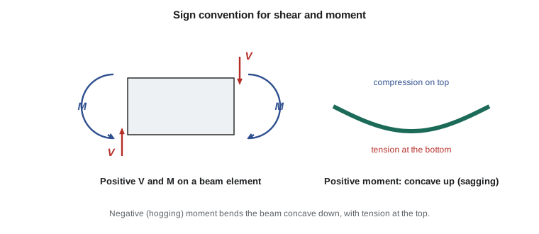
With this convention, a simply supported beam under downward loads has positive (sagging) moment everywhere, and a cantilever under downward loads has negative (hogging) moment. Structural engineers care about the sign because it tells them which face is in tension. A concrete beam needs its reinforcing steel on the tension face, at the bottom in sagging regions and at the top in hogging regions over supports.
Shear and moment by the method of sections
The direct way to find \(V(x)\) and \(M(x)\) is to cut the beam at a general position, draw the free-body diagram of the left piece, and write equilibrium. Wherever the loading changes (at a point load, the start or end of a distributed load, or a couple), you need a new cut, so a beam with several loads has several segments, each with its own equations.
Worked problem
Simply supported beam with a uniform load
A simply supported beam of span \(L\) carries a uniform load \(w\) (force per unit length) over its full length. Find \(V(x)\), \(M(x)\) and the maximum moment.
Show solution
- By symmetry each reaction is \(R = wL/2\).
- Cut at \(x\). The left piece carries the reaction \(wL/2\) upward and a load \(wx\) downward. Vertical equilibrium:
- \[V(x) = \frac{wL}{2} - w\,x\]
- Moments about the cut, with the load \(wx\) acting at \(x/2\):
- \[M(x) = \frac{wL}{2}\,x - \frac{w\,x^2}{2}\]
- The moment is greatest where \(dM/dx = V = 0\), at \(x = L/2\):
- \[M_{\max} = \frac{wL}{2}\cdot\frac{L}{2} - \frac{w}{2}\cdot\frac{L^2}{4} = \frac{wL^2}{8}\]
Answer: The shear varies linearly from \(+wL/2\) to \(-wL/2\), and the moment is a parabola with maximum \(wL^2/8\) at midspan, one of the most used results in structural engineering.
Relations between load, shear and moment
Writing equations for every segment is slow. A faster method uses three relations that come from equilibrium of a short beam element of length \(dx\) carrying a distributed load \(w(x)\), taken positive downward:
In words: the slope of the shear diagram equals the negative of the load intensity, and the slope of the moment diagram equals the shear. Integrating between two points gives the change in each quantity:
So the change in shear between two points equals the negative of the load area between them, and the change in moment equals the area under the shear diagram. Concentrated loads and couples cause jumps: a downward point load \(P\) makes the shear drop by \(P\), and a clockwise couple \(M_0\) makes the moment jump up by \(M_0\) (moving left to right).
These rules give the shapes of the diagrams at a glance.
- No load between two points: shear constant, moment linear.
- Uniform load: shear linear, moment parabolic (a second-degree curve).
- Linearly varying load: shear parabolic, moment cubic.
- Maximum or minimum moment occurs where the shear is zero or changes sign, or at a point load or couple.
The area method step by step
Here is a reliable procedure for drawing both diagrams.
- Find all the reactions from equilibrium of the whole beam, and check them with a second equation.
- Start at the left end with \(V = 0\) and \(M = 0\) (unless there is a fixed support or couple there). Move right.
- At each point load or reaction, jump the shear by the force. Between loads, change the shear by the negative of the load area.
- Sketch the moment diagram using the shear: its slope equals the shear, and its change equals the shear area.
- Locate where the shear crosses zero; that is where the moment peaks. Find the moment there.
- Check that you finish at the right end with \(V\) and \(M\) consistent with the support there (both zero at a free end or a simple support with no couple).
Worked problem
Point load plus a partial uniform load
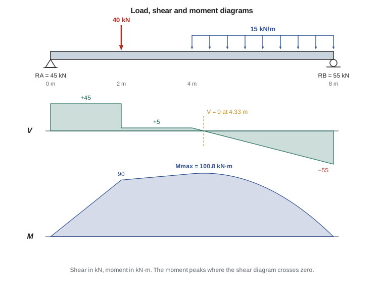
A simply supported beam AB has a span of 8 m. It carries a point load of 40 kN at 2 m from A and a uniform load of 15 kN/m over the right 4 m (from 4 m to 8 m). Draw the shear and moment diagrams and find the maximum moment.
Show solution
- Reactions. Total UDL = \(15 \times 4 = 60\ \text{kN}\) acting at 6 m. Moments about A: \(8R_B = 40(2) + 60(6) = 440\), so \(R_B = 55\ \text{kN}\) and \(R_A = 100 - 55 = 45\ \text{kN}\).
- Shear: \(V = +45\) from A to 2 m; drops by 40 to \(+5\) from 2 m to 4 m; then decreases at 15 kN/m from \(+5\) to \(5 - 60 = -55\) at B, matching \(R_B\).
- Zero shear under the UDL: \(5 - 15(x - 4) = 0\) gives \(x = 4.333\ \text{m}\).
- Moments from shear areas: \(M(2) = 45 \times 2 = 90\ \text{kN·m}\); \(M(4) = 90 + 5 \times 2 = 100\ \text{kN·m}\).
- From 4 m to 4.333 m the shear area is a triangle: \(\tfrac{1}{2}(5)(0.333) = 0.83\), so \(M_{\max} = 100.8\ \text{kN·m}\).
- Check: from 4.333 m to 8 m, the area is \(\tfrac{1}{2}(-55)(3.667) = -100.8\), returning \(M\) to zero at B.
Answer: The maximum moment is about 100.8 kN·m at 4.33 m from A. The diagrams close to zero at B, which confirms the arithmetic.
The closing check in the last step is worth doing every time. If the moment does not return to zero at a simple support, a reaction or an area is wrong.
Worked problem
Cantilever with a uniform load and a tip load
A cantilever of length 3 m is fixed at A (left end) and carries a uniform load of 8 kN/m over its length and a point load of 12 kN at the free end B. Find the shear and moment at the fixed end.
Show solution
- Work from the free end, where \(V = 0\) and \(M = 0\) before the loads. Cutting at distance \(s\) from B and taking the piece to the right of the cut:
- \[V = 12 + 8s \qquad M = -12s - \frac{8s^2}{2}\]
- At the support, \(s = 3\ \text{m}\): \(V = 12 + 24 = 36\ \text{kN}\) and \(M = -36 - 36 = -72\ \text{kN·m}\).
Answer: The fixed end carries 36 kN of shear and a hogging moment of 72 kN·m. The negative sign shows tension at the top, which is where a concrete cantilever needs its main reinforcement.
Worked problem
A floor beam in US customary units
A simply supported steel floor beam spans 24 ft and carries a uniform load of 1.2 kips/ft (dead plus live). Find the reactions, the maximum shear and the maximum moment.
Show solution
- Total load \(W = 1.2 \times 24 = 28.8\ \text{kips}\); each reaction is \(14.4\ \text{kips}\), which is also the maximum shear.
- \[M_{\max} = \frac{wL^2}{8} = \frac{1.2 \times 24^2}{8} = 86.4\ \text{kip·ft}\]
- In the units steel designers use for section properties: \(86.4 \times 12 = 1\,037\ \text{kip·in.}\)
Answer: Reactions and maximum shear 14.4 kips, maximum moment 86.4 kip·ft at midspan. The conversion to kip·in. matters, because section moduli are tabulated in cubic inches.
Overhangs and points of inflection
When a beam overhangs a support, the overhang creates a hogging moment over the support, while the span between supports may still sag. The moment diagram then crosses zero at a point of inflection (or contraflexure), where the curvature of the deflected beam changes direction. In reinforced concrete, the reinforcement must change faces near these points, and in steel the compression flange switches from top to bottom, which affects lateral stability. Overhangs are often used deliberately because the hogging moment over the support reduces the sagging moment in the span.
Computing diagrams numerically
For complicated loadings, engineers use software, and even a few lines of code can produce the diagrams. The program below uses the equilibrium of the left-hand piece directly: at each position it adds the effects of the reactions and loads to the left. It reproduces the worked example and finds the maximum moment by scanning the span finely.
# Shear and moment along a simply supported beam (kN, m); downward loads positive
L = 8.0
points = [(2.0, 40.0)]                # (position, load)
udls = [(4.0, 8.0, 15.0)]             # (start, end, intensity)

# Reactions from moments about A and vertical equilibrium
total = sum(P for _, P in points) + sum(w * (b - a) for a, b, w in udls)
mom_A = sum(P * x for x, P in points) + sum(w * (b - a) * (a + b) / 2 for a, b, w in udls)
RB = mom_A / L
RA = total - RB

def V_M(x):
    V, M = RA, RA * x
    for xp, P in points:
        if xp < x:
            V -= P; M -= P * (x - xp)
    for a, b, w in udls:
        if x > a:
            l = min(x, b) - a                 # loaded length left of the cut
            V -= w * l; M -= w * l * (x - a - l / 2)
    return V, M

print(f"RA = {RA:.1f} kN, RB = {RB:.1f} kN")
for x in [0, 1, 2.5, 3, 4, 5, 6, 7, 8]:
    V, M = V_M(x)
    print(f"x = {x:5.2f} m   V = {V:7.2f} kN   M = {M:7.2f} kN*m")
xs = [i * L / 8000 for i in range(8001)]
Mmax, xmax = max((V_M(x)[1], x) for x in xs)
print(f"Maximum moment {Mmax:.2f} kN*m at x = {xmax:.3f} m")RA = 45.0 kN, RB = 55.0 kN x = 0.00 m V = 45.00 kN M = 0.00 kN*m x = 1.00 m V = 45.00 kN M = 45.00 kN*m x = 2.50 m V = 5.00 kN M = 92.50 kN*m x = 3.00 m V = 5.00 kN M = 95.00 kN*m x = 4.00 m V = 5.00 kN M = 100.00 kN*m x = 5.00 m V = -10.00 kN M = 97.50 kN*m x = 6.00 m V = -25.00 kN M = 80.00 kN*m x = 7.00 m V = -40.00 kN M = 47.50 kN*m x = 8.00 m V = -55.00 kN M = 0.00 kN*m Maximum moment 100.83 kN*m at x = 4.333 m
Scanning at 1 mm intervals finds the peak to well within drafting accuracy. Structural analysis programs do the same job with exact expressions, but the principle is the method of sections you have just used by hand.
Common mistakes
MistakeReplacing a distributed load by its resultant when computing internal shear and moment at a cut inside the loaded length.
InsteadOnly the part of the load on one side of the cut acts on that free body. Use its own resultant, at its own centroid.
MistakeLooking for maximum moment only at point loads.
InsteadAlso check where the shear diagram crosses zero, which happens inside distributed loads.
MistakeForgetting the jump in moment at a concentrated couple.
InsteadA couple changes the moment suddenly but does not change the shear.
MistakeMixing kN·m and kN·mm, or kip·ft and kip·in., when moving to stress calculations.
InsteadConvert the moment to the units of the section properties before using the flexure formula.
Summary and key terms
- Simply supported beams, cantilevers and overhanging beams are statically determinate.
- Positive moment sags the beam (tension at the bottom); positive shear rotates an element clockwise.
- \(dV/dx = -w\) and \(dM/dx = V\): load area changes the shear and shear area changes the moment.
- Point loads cause jumps in shear; couples cause jumps in moment.
- Maximum moment occurs where the shear is zero or changes sign.
- A simply supported beam under a uniform load has \(M_{\max} = wL^2/8\); a cantilever with a tip load has \(M_{\max} = PL\) at the support.
- Simply supported beam
- A beam with a pin at one end and a roller at the other.
- Cantilever
- A beam fixed at one end and free at the other.
- Uniformly distributed load
- A load of constant intensity along a length, in force per unit length.
- Shear force diagram
- A plot of internal shear force along a beam.
- Bending moment diagram
- A plot of internal bending moment along a beam.
- Sagging moment
- Positive moment that bends a beam concave upward.
- Hogging moment
- Negative moment that bends a beam concave downward.
- Point of inflection
- A point where the bending moment, and the curvature, change sign.
Practice problems
Work each problem on paper first, then reveal the answer to check.
A simply supported 6 m beam carries 20 kN/m. Find \(M_{\max}\).
Show answer
\(wL^2/8 = 20 \times 36/8 = 90\ \text{kN·m}\).
A simply supported beam of span \(L\) carries a point load \(P\) at midspan. Find \(M_{\max}\).
Show answer
\(PL/4\).
A 2.5 m cantilever carries a 10 kN tip load. Find the moment at the support.
Show answer
\(M = -10 \times 2.5 = -25\ \text{kN·m}\) (hogging).
Between two point loads with no distributed load, what shapes do the diagrams have?
Show answer
Constant shear and linear moment.
The shear diagram crosses zero at \(x = 3.2\ \text{m}\) under a UDL. What does that tell you?
Show answer
The bending moment has a local maximum (or minimum) there.
Why must the moment diagram close at zero at a simple support?
Show answer
A pin or roller cannot resist moment, so the internal moment there is zero (unless a couple is applied there).
Lesson quiz · 5 questions
Score 60% or more to complete this lesson.
Create a free account to save your progress, take quizzes and earn a certificate.