
MEC-200 · Lesson 3 of 12 · 29 min
Torsion of circular shafts
A torque is a moment about a member's own axis. Drive shafts in pumps and turbines, the shafts of motors that drive conveyors and lift gates, drilled piles twisted into the ground, and steel tubes in sign structures all carry torque. In buildings and bridges, torsion also arises when loads act off the shear center of a beam, as in a spandrel beam that supports a floor slab on one side only.
This lesson develops the theory for circular shafts, solid or hollow, where the results are exact within the elastic range and remarkably simple. It then shows how to transmit power, how to handle shafts with several segments or redundant supports, and how thin-walled closed sections resist torque.
How a circular shaft deforms
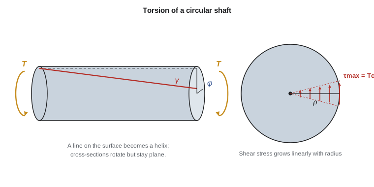
Draw a grid of lines on the surface of a rubber rod and twist it. The circles around the rod stay circles and stay the same size, and the cross-sections stay flat and simply rotate relative to one another. Straight lines along the rod become helices. These observations, which can be proved by symmetry for any circular shaft, lead to the key geometric result.
Consider a shaft of length \(L\) whose end rotates by an angle \(\phi\) (the angle of twist, in radians) relative to the other end. A line on the surface at radius \(c\) tilts by an angle \(\gamma\), which is the shear strain. For a small angle, the arc length at the end is \(c\,\phi = L\,\gamma\), so the shear strain at the surface is \(\gamma_{\max} = c\,\phi/L\). At any interior radius \(\rho\) (rho), the same reasoning gives
Shear strain grows linearly from zero at the center to a maximum at the outer surface. If the material is linear elastic, \(\tau = G\gamma\), so the shear stress also varies linearly with radius.
The torsion formula
Equilibrium connects the stress to the torque. A ring of area \(dA\) at radius \(\rho\) carries a shear force \(\tau\,dA\), which has a moment \(\rho\,\tau\,dA\) about the axis. Adding these up over the section must give the internal torque \(T\). With \(\tau = \tau_{\max}\,\rho/c\):
The integral \(J\) is the polar moment of inertia of the cross-section. Rearranging gives the torsion formula:
For a solid circular section of radius \(c\) (diameter \(d\)), and for a hollow tube with outer and inner radii \(c_o\) and \(c_i\):
Because \(J\) depends on the fourth power of the radius, material far from the center is very effective. The material near the center carries little stress and contributes little to \(J\), which is why hollow shafts are lighter for the same strength. Long drive shafts in vehicles and the tubular members of sign gantries take advantage of this.
Shear stresses on the cross-section are accompanied, by equilibrium of a small element, by equal shear stresses on longitudinal planes. That has practical consequences. A wooden shaft, weak in shear along the grain, splits lengthwise. A brittle material such as chalk or cast iron fails on a helix at 45° to the axis, because the 45° planes carry the maximum tensile stress, as lesson 8 will show. Twist a piece of chalk and you will see the helical fracture.
Worked problem
Solid versus hollow shafts
A solid steel shaft of diameter 60 mm carries a torque of 3.0 kN·m. (a) Find the maximum shear stress. (b) A hollow shaft with outer diameter 70 mm is to carry the same torque at the same maximum stress. Find its inner diameter and compare the weights.
Show solution
- (a) \(J = \pi (60)^4/32 = 1.272 \times 10^6\ \text{mm}^4\), \(c = 30\ \text{mm}\), \(T = 3.0 \times 10^6\ \text{N·mm}\).
- \[\tau_{\max} = \frac{(3.0 \times 10^6)(30)}{1.272 \times 10^6} = 70.7\ \text{MPa}\]
- (b) Require \(J/c_o = J_{\text{solid}}/c = 1.272 \times 10^6/30 = 42\,410\ \text{mm}^3\), so \(J = 42\,410 \times 35 = 1.484 \times 10^6\ \text{mm}^4\).
- \[\frac{\pi}{2}(35^4 - c_i^4) = 1.484 \times 10^6 \quad\Rightarrow\quad c_i^4 = 1.501 \times 10^6 - 0.945 \times 10^6\]
- So \(c_i^4 = 0.556 \times 10^6\ \text{mm}^4\), \(c_i = 27.3\ \text{mm}\), inner diameter about 54.6 mm.
- Areas: solid \(\pi (30)^2 = 2\,827\ \text{mm}^2\); hollow \(\pi(35^2 - 27.3^2) = 1\,507\ \text{mm}^2\).
Answer: The solid shaft is stressed to 70.7 MPa. A 70 mm tube with a 54.6 mm bore does the same job with about 53 % of the weight.
Angle of twist
Combining \(\gamma = \rho\phi/L\), \(\tau = G\gamma\) and \(\tau = T\rho/J\) gives the angle of twist for a uniform shaft carrying a constant internal torque:
The product \(GJ\) is the torsional rigidity, the torsional counterpart of the axial rigidity \(AE\). The angle is in radians. Limiting twist matters for machinery, where too much twist causes vibration and misalignment, and for structures, where twist of a beam can crack finishes or damage connections. A common rule for line shafting is a twist of no more than about 1° over a length of 20 diameters, although specific limits depend on the application.
For shafts with several segments, or with several gears applying torques along their length, use the same bookkeeping as for axial bars: find the internal torque in each segment with the method of sections, then add the segment twists, \(\phi = \sum T_iL_i/(G_iJ_i)\). Use the right-hand rule for signs: a torque whose vector points out of the cut face is positive.
Power transmission
Shafts usually exist to transmit power. Power is torque times angular speed:
With \(T\) in N·m and \(\omega\) in rad/s, \(P\) is in watts. Rotational speed is often given in revolutions per minute (rpm), so \(\omega = 2\pi n/60\). At a given power, the torque is inversely proportional to speed. That is why a gearbox that slows a motor down to drive a heavy load needs a much thicker output shaft than input shaft.
Worked problem
Sizing a pump shaft
A pump requires 45 kW at 1,750 rpm. The steel shaft is to have a maximum shear stress of no more than 55 MPa. Find the minimum diameter of a solid shaft.
Show solution
- \[\omega = \frac{2\pi (1750)}{60} = 183.3\ \text{rad/s}\]
- \[T = \frac{P}{\omega} = \frac{45\,000}{183.3} = 245.5\ \text{N·m} = 245.5 \times 10^3\ \text{N·mm}\]
- For a solid shaft, \(\tau_{\max} = Tc/J = 16T/(\pi d^3)\).
- \[d^3 = \frac{16\,T}{\pi\,\tau_{\text{allow}}} = \frac{16 \times 245.5 \times 10^3}{\pi \times 55} = 22\,730\ \text{mm}^3\]
- \(d = 28.3\ \text{mm}\).
Answer: A 30 mm shaft, the next standard size up, would be selected, subject to a check of keyways, bending from belt or gear loads and fatigue.
Worked problem
A shaft in US customary units
A motor delivers 60 hp at 1,200 rpm through a solid steel shaft (\(G = 11\,200\ \text{ksi}\)) 40 in. long with a diameter of 1.75 in. Find the maximum shear stress and the angle of twist.
Show solution
- Torque from power: \(T = 63\,025 \times \text{hp}/n = 63\,025 \times 60/1200 = 3\,151\ \text{lb·in.}\) (the constant 63,025 converts horsepower and rpm to lb·in.).
- \[J = \frac{\pi (1.75)^4}{32} = 0.9208\ \text{in.}^4\]
- \[\tau_{\max} = \frac{(3\,151)(0.875)}{0.9208} = 2\,994\ \text{psi} \approx 3.0\ \text{ksi}\]
- \[\phi = \frac{T\,L}{G\,J} = \frac{(3\,151)(40)}{(11.2 \times 10^6)(0.9208)} = 0.0122\ \text{rad} = 0.70°\]
Answer: About 3.0 ksi and 0.70°. The stress is low, but a long shaft at this diameter might be governed by twist or by bending from the drive pulley.
Statically indeterminate shafts
A shaft fixed at both ends and loaded by a torque between them is statically indeterminate, exactly like the axial bar between two walls in lesson 2. The method is identical: equilibrium of torques, a compatibility condition that the total twist between the fixed ends is zero, and the torque–twist relation \(\phi = TL/(GJ)\).
Worked problem
A shaft fixed at both ends
A uniform solid shaft of length 1.2 m is fixed at both ends A and B. A torque of 1.8 kN·m is applied at C, 0.4 m from A. Find the reactive torques at the two ends.
Show solution
- Equilibrium: \(T_A + T_B = 1.8\ \text{kN·m}\).
- Compatibility: the twist of AC must equal and cancel the twist of CB, so \(T_A(0.4)/(GJ) = T_B(0.8)/(GJ)\), giving \(T_A = 2\,T_B\).
- Substituting: \(3\,T_B = 1.8\), so \(T_B = 0.6\ \text{kN·m}\) and \(T_A = 1.2\ \text{kN·m}\).
Answer: The nearer support A carries 1.2 kN·m and B carries 0.6 kN·m. The result \(T_A = T\,b/L\) has the same form as the axial case.
Compound shafts, such as a steel core inside a bonded aluminum sleeve, are also indeterminate. Both parts twist through the same angle, so the torque divides in proportion to their torsional rigidities \(GJ\), just as load divided in proportion to \(AE\) in the composite post.
Thin-walled closed sections and noncircular shafts
For noncircular sections, the cross-sections warp out of plane when twisted, and the simple formulas no longer apply. Solid rectangular bars, for example, have their maximum shear stress at the middle of the long side, not at the corners, and their stiffness is much lower than a circle of equal area. Open sections such as I-beams and channels are especially weak and flexible in torsion, which is why they are poor choices for members that must resist twisting.
Thin-walled closed tubes of any shape, such as rectangular hollow structural sections and box girders, are an important exception. They resist torque efficiently through a constant shear flow \(q = \tau\,t\) around the wall. Equilibrium gives Bredt's formula:
where \(A_m\) is the area enclosed by the centerline of the wall and \(t\) is the local wall thickness. The highest stress occurs where the wall is thinnest. Box girders in curved highway bridges rely on this closed-section behavior to carry the large torques produced by the curvature.
Designing a shaft with code
In practice a shaft must satisfy both a stress limit and a twist limit, and the governing one depends on its length. The program below sizes a solid steel shaft for a given power and speed against both criteria and reports which one controls.
# Size a solid steel shaft for power, stress and twist limits
import math

G = 77000.0                 # MPa (N/mm^2)
tau_allow = 55.0            # MPa
def size_shaft(power_kW, rpm, length_m, twist_limit_deg_per_m=0.25):
    T = power_kW * 1e6 / (2 * math.pi * rpm / 60)          # N*mm
    d_stress = (16 * T / (math.pi * tau_allow)) ** (1 / 3)
    phi_allow = math.radians(twist_limit_deg_per_m * length_m)
    # phi = T L / (G J) with J = pi d^4 / 32  ->  d^4 = 32 T L / (pi G phi)
    d_twist = (32 * T * length_m * 1000 / (math.pi * G * phi_allow)) ** 0.25
    d = max(d_stress, d_twist)
    rule = "stress" if d_stress >= d_twist else "twist"
    print(f"{power_kW:5.0f} kW at {rpm:5.0f} rpm: T = {T/1e6:6.3f} kN*m  "
          f"d(stress) = {d_stress:5.1f} mm  d(twist) = {d_twist:5.1f} mm  -> {rule} governs, use {math.ceil(d/5)*5} mm")

size_shaft(45, 1750, 1.5)
size_shaft(45, 300, 1.5)
size_shaft(200, 900, 4.0)
print("Same shafts with a looser limit of 2.0 degrees per m:")
size_shaft(45, 1750, 1.5, 2.0)
size_shaft(45, 300, 1.5, 2.0)
size_shaft(200, 900, 4.0, 2.0)45 kW at 1750 rpm: T = 0.246 kN*m d(stress) = 28.3 mm d(twist) = 52.2 mm -> twist governs, use 55 mm 45 kW at 300 rpm: T = 1.432 kN*m d(stress) = 51.0 mm d(twist) = 81.2 mm -> twist governs, use 85 mm 200 kW at 900 rpm: T = 2.122 kN*m d(stress) = 58.1 mm d(twist) = 89.6 mm -> twist governs, use 90 mm Same shafts with a looser limit of 2.0 degrees per m: 45 kW at 1750 rpm: T = 0.246 kN*m d(stress) = 28.3 mm d(twist) = 31.1 mm -> twist governs, use 35 mm 45 kW at 300 rpm: T = 1.432 kN*m d(stress) = 51.0 mm d(twist) = 48.3 mm -> stress governs, use 55 mm 200 kW at 900 rpm: T = 2.122 kN*m d(stress) = 58.1 mm d(twist) = 53.3 mm -> stress governs, use 60 mm
With the strict limit of 0.25° per meter, typical of precision line shafting, twist governs every case. Because the limit is stated per meter, the shaft length cancels out of the twist criterion. With a looser limit of 2° per meter, the required twist diameters shrink by a factor of \(8^{1/4} \approx 1.68\), and stress governs the two high-torque shafts. Changing the inputs and watching which criterion controls is a quick way to build engineering judgment.
Keyways, shoulders and fatigue
Real shafts are not smooth cylinders. Gears and pulleys are fixed with keys that sit in keyways cut into the shaft, bearings sit against shoulders where the diameter changes, and retaining rings sit in grooves. Each of these raises the local shear stress above \(Tc/J\) by a stress concentration factor, just as holes did for axial members in lesson 2. A shoulder with a generous fillet radius may have a factor only slightly above 1, while a sharp-cornered keyway can approach 2 or more.
Rotating shafts that also carry bending from belts or gears see a full reversal of bending stress every revolution, so a shaft turning at 1,750 rpm accumulates millions of cycles in a few days. Fatigue, not static strength, therefore governs most machine shafts, and the cracks almost always start at keyways, fillets and grooves. The allowable stress of 55 MPa used in the examples above is deliberately conservative to allow for these effects in a preliminary design. A full shaft design combines torsion with bending, as lesson 7 shows, and then checks fatigue at each discontinuity.
Common mistakes
MistakeUsing the diameter instead of the radius for \(c\) in \(\tau = Tc/J\).
Instead\(c\) is the outer radius. With diameter, use \(\tau = 16T/(\pi d^3)\) for a solid shaft.
MistakeLeaving the angle of twist in radians when a limit is in degrees, or the reverse.
Instead\(\phi = TL/(GJ)\) gives radians. Multiply by \(180/\pi\) to compare with a limit in degrees.
MistakeUsing rpm directly as \(\omega\) in \(P = T\omega\).
InsteadConvert: \(\omega = 2\pi n/60\) rad/s.
MistakeApplying the circular-shaft formulas to an I-beam or channel.
InsteadOpen and noncircular sections warp; they need different formulas and are much weaker in torsion.
Summary and key terms
- In a twisted circular shaft, shear strain and stress vary linearly from zero at the center to a maximum at the surface.
- The torsion formula is \(\tau = T\rho/J\), with \(J = \pi d^4/32\) for a solid shaft.
- The angle of twist is \(\phi = TL/(GJ)\); \(GJ\) is the torsional rigidity.
- Power and torque are related by \(P = T\omega\), so low-speed shafts carry large torques.
- Indeterminate shafts use equilibrium, twist compatibility and \(\phi = TL/(GJ)\).
- Thin-walled closed sections carry torque by shear flow \(q = T/(2A_m)\); open sections are weak in torsion.
- Torque
- A moment about a member's longitudinal axis.
- Polar moment of inertia
- The integral of the squared distance from the axis over the cross-section, J.
- Angle of twist
- The relative rotation of two cross-sections of a shaft, in radians.
- Torsional rigidity
- The product GJ, which governs how much a shaft twists under torque.
- Shear flow
- Shear force per unit length along a thin wall, the product of shear stress and thickness.
- Warping
- Out-of-plane distortion of a cross-section under torque, which occurs in noncircular sections.
- Bredt's formula
- The relation between torque and shear flow in a thin-walled closed section.
Practice problems
Work each problem on paper first, then reveal the answer to check.
A 50 mm solid shaft carries 1.5 kN·m. Find \(\tau_{\max}\).
Show answer
\(16T/(\pi d^3) = 16 \times 1.5 \times 10^6/(\pi \times 125\,000) = 61.1\ \text{MPa}\).
By what factor does \(\tau_{\max}\) change if a solid shaft's diameter is doubled under the same torque?
Show answer
It falls to \(1/8\), because \(\tau \propto 1/d^3\).
A 2.0 m steel shaft (\(G = 77\ \text{GPa}\), \(J = 1.0 \times 10^6\ \text{mm}^4\)) carries 1.0 kN·m. Find the twist in degrees.
Show answer
\(\phi = 10^6 \times 2000/(77\,000 \times 10^6) = 0.0260\ \text{rad} = 1.49°\).
A motor gives 15 kW at 3,000 rpm. What torque does its shaft carry?
Show answer
\(\omega = 314.2\ \text{rad/s}\), \(T = 15\,000/314.2 = 47.7\ \text{N·m}\).
A rectangular steel tube 200 mm by 100 mm on its wall centerline, 8 mm thick, carries 20 kN·m. Estimate the shear stress.
Show answer
\(A_m = 20\,000\ \text{mm}^2\); \(\tau = 20 \times 10^6/(2 \times 20\,000 \times 8) = 62.5\ \text{MPa}\).
Why does chalk fail on a 45° helix when twisted?
Show answer
Pure shear produces maximum tension on 45° planes, and chalk is weak in tension.
Lesson quiz · 5 questions
Score 60% or more to complete this lesson.
Create a free account to save your progress, take quizzes and earn a certificate.