
MEC-200 · Lesson 10 of 12 · 29 min
Beam deflection by integration
A beam can be strong enough and still be unsatisfactory. A floor that sags visibly, bounces underfoot, cracks the plaster or tile below it, or makes doors stick is a failure of serviceability, not strength. Long-span roofs can pond rainwater if they deflect too much, which adds more load and more deflection. Bridges must stay within deflection limits so that joints, bearings and drainage work. Deflection also matters for analysis: the indeterminate beams of lesson 11 are solved by using deflections as compatibility conditions. This lesson derives the differential equation of the deflected beam and solves it by direct integration.
The elastic curve
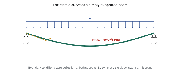
When a beam bends, its neutral axis takes up a curved shape called the elastic curve. Let \(v(x)\) be the deflection of the neutral axis at position \(x\), positive upward, and let \(\theta(x) = dv/dx\) be its slope. Lesson 5 showed that the curvature is related to the bending moment by
From geometry, the exact curvature of a curve \(v(x)\) is \(v''/(1 + v'^2)^{3/2}\). For real beams the slopes are tiny, typically less than 0.01 radians, so \(v'^2\) is negligible next to 1 and the curvature is simply \(v''\). That gives the differential equation of the elastic curve:
With the sign convention of lesson 4, a positive (sagging) moment gives positive curvature, a curve that is concave upward. Differentiating twice more, using \(dM/dx = V\) and \(dV/dx = -w\), gives two equivalent forms: \(EI\,v''' = V(x)\) and \(EI\,v'''' = -w(x)\). The second-order form is used most often in hand calculations, because the moment equation is usually easy to write.
Boundary and continuity conditions
Integrating \(EIv'' = M\) once gives the slope and twice gives the deflection, with two constants of integration. The constants come from what the supports enforce.
- At a pin or roller, the deflection is zero: \(v = 0\).
- At a fixed support, both the deflection and the slope are zero: \(v = 0\) and \(v' = 0\).
- At a free end, the deflection and slope are unknown, but the moment and shear are zero, which the moment equation already reflects.
- At a plane of symmetry, the slope is zero.
When the moment equation changes from one segment to the next, at a point load for example, each segment has its own two constants. The extra equations come from continuity: at the junction between segments, the beam cannot have a kink or a break, so the slope and deflection computed from both sides must be equal.
Cantilever with an end load
Worked problem
Deflection of a cantilever
A cantilever of length \(L\) is fixed at \(x = 0\) and carries a downward load \(P\) at its free end, \(x = L\). Find the equation of the elastic curve, the tip deflection and the tip slope.
Show solution
- Moment at a section \(x\), taking the piece to the right: \(M(x) = -P(L - x)\).
- \[E I\,v'' = -P(L - x)\]
- Integrate once: \(E I\,v' = -P(Lx - x^2/2) + C_1\). At the fixed end \(v'(0) = 0\), so \(C_1 = 0\).
- Integrate again: \(E I\,v = -P(Lx^2/2 - x^3/6) + C_2\). At the fixed end \(v(0) = 0\), so \(C_2 = 0\).
- \[v(x) = -\frac{P\,x^2}{6\,E I}(3L - x)\]
- \[v_{\text{tip}} = v(L) = -\frac{P\,L^3}{3\,E I} \qquad \theta_{\text{tip}} = v'(L) = -\frac{P\,L^2}{2\,E I}\]
Answer: The tip deflects downward by \(PL^3/(3EI)\). Note the cube on the length: doubling the length of a cantilever makes it eight times as flexible.
Simply supported beam with a uniform load
Worked problem
The most used deflection formula
A simply supported beam of span \(L\) carries a uniform load \(w\). Find the elastic curve and the maximum deflection.
Show solution
- From lesson 4: \(M(x) = wLx/2 - wx^2/2\).
- \[E I\,v'' = \frac{wL}{2}x - \frac{w}{2}x^2\]
- \[E I\,v' = \frac{wL}{4}x^2 - \frac{w}{6}x^3 + C_1 \qquad E I\,v = \frac{wL}{12}x^3 - \frac{w}{24}x^4 + C_1x + C_2\]
- At \(x = 0\), \(v = 0\), so \(C_2 = 0\). At \(x = L\), \(v = 0\): \(wL^4/12 - wL^4/24 + C_1L = 0\), so \(C_1 = -wL^3/24\).
- \[v(x) = -\frac{w\,x}{24\,E I}(L^3 - 2Lx^2 + x^3)\]
- \[v_{\max} = v\Big(\frac{L}{2}\Big) = -\frac{5\,w\,L^4}{384\,E I}\]
Answer: The maximum deflection at midspan is \(5wL^4/(384EI)\), and the end slopes are \(\pm wL^3/(24EI)\). This result is used in nearly every floor and roof design.
The fourth power of the span in that formula is the reason serviceability so often governs long beams. A beam that is adequate for strength at a 6 m span may be far too flexible at 9 m: the moment increases by \((9/6)^2 = 2.25\), but the deflection by \((9/6)^4 = 5.1\).
| Beam and load | Maximum deflection | Location |
|---|---|---|
| Cantilever, end load P | \(PL^3/(3EI)\) | Free end |
| Cantilever, uniform load w | \(wL^4/(8EI)\) | Free end |
| Simple span, central load P | \(PL^3/(48EI)\) | Midspan |
| Simple span, uniform load w | \(5wL^4/(384EI)\) | Midspan |
| Simple span, end couple M at one end | \(ML^2/(9\sqrt{3}\,EI)\) | \(0.423L\) from the loaded end |
| Fixed–fixed, uniform load w | \(wL^4/(384EI)\) | Midspan |
Beams with several segments and singularity functions
When a point load sits partway along a beam, the moment equation changes at the load, and direct integration needs two sets of constants plus continuity conditions. For several loads this becomes tedious. Singularity functions, also called Macaulay brackets, let you write a single moment equation valid along the whole beam. The bracket \(\langle x - a \rangle^n\) is defined as \((x - a)^n\) when \(x \ge a\) and zero when \(x < a\). It is integrated like an ordinary power:
Using brackets, a point load \(P\) at \(x = a\) contributes \(-P\langle x - a\rangle\) to the moment, a uniform load starting at \(a\) contributes \(-w\langle x - a\rangle^2/2\), and a clockwise couple \(M_0\) at \(a\) contributes \(M_0\langle x - a\rangle^0\). Because each term switches on only beyond its load, one equation and two constants cover the whole beam.
Worked problem
A point load off center
A simply supported steel beam of span 6 m (\(E = 200\ \text{GPa}\), \(I = 80 \times 10^6\ \text{mm}^4\)) carries a load of 50 kN at 2 m from the left support A. Find the deflection under the load.
Show solution
- Reactions: \(R_A = 50 \times 4/6 = 33.33\ \text{kN}\), \(R_B = 16.67\ \text{kN}\).
- \[E I\,v'' = 33.33\,x - 50\langle x - 2\rangle \quad (\text{kN, m})\]
- \[E I\,v = \frac{33.33}{6}x^3 - \frac{50}{6}\langle x - 2\rangle^3 + C_1x + C_2\]
- \(v(0) = 0\) gives \(C_2 = 0\). \(v(6) = 0\): \(5.556(216) - 8.333(64) + 6C_1 = 0\), so \(C_1 = -111.1\ \text{kN·m}^2\).
- At \(x = 2\): \(E I\,v = 5.556(8) - 0 - 111.1(2) = -177.8\ \text{kN·m}^3\).
- \(EI = 200 \times 10^6\ \text{kN/m}^2 \times 80 \times 10^{-6}\ \text{m}^4 = 16\,000\ \text{kN·m}^2\), so \(v(2) = -177.8/16\,000 = -0.0111\ \text{m}\).
Answer: The beam deflects 11.1 mm under the load. The maximum deflection is slightly larger and occurs a little closer to midspan, where the slope is zero; the code below finds it.
Worked problem
A floor beam deflection in US customary units
The 24 ft W14×26 floor beam from lessons 4 and 5 (\(I = 245\ \text{in.}^4\), \(E = 29\,000\ \text{ksi}\)) carries a live load of 0.8 kips/ft out of its total 1.2 kips/ft. Find the live-load deflection and compare it with a limit of \(L/360\).
Show solution
- Units: \(w = 0.8/12 = 0.0667\ \text{kips/in.}\), \(L = 288\ \text{in.}\)
- \[\Delta = \frac{5\,w\,L^4}{384\,E I} = \frac{5(0.0667)(288)^4}{384(29\,000)(245)} = 0.84\ \text{in.}\]
- Limit: \(L/360 = 288/360 = 0.80\ \text{in.}\)
Answer: The live-load deflection of 0.84 in. slightly exceeds \(L/360\), even though the bending stress was only 59 % of yield. Deflection, not strength, would govern this beam, and the next heavier section would be chosen.
Worked problem
Sizing a joist for stiffness
The 38 × 235 mm timber joist from lesson 5 spans 4.0 m and carries a specified live load of 1.2 kN/m (part of its 1.6 kN/m total). With \(E = 9\,500\ \text{MPa}\), find the live-load deflection, compare it with span/360, and find the second moment of area that would be needed to meet span/480 instead.
Show solution
- \(I = 38(235)^3/12 = 41.1 \times 10^6\ \text{mm}^4\); \(w = 1.2\ \text{N/mm}\); \(L = 4\,000\ \text{mm}\).
- \[\Delta = \frac{5\,w\,L^4}{384\,E I} = \frac{5(1.2)(4000)^4}{384(9500)(41.1 \times 10^6)} = 10.2\ \text{mm}\]
- Span/360 \(= 11.1\ \text{mm}\), so the joist passes. Span/480 \(= 8.33\ \text{mm}\), so it does not.
- Deflection is inversely proportional to \(I\): required \(I = 41.1 \times 10^6 \times 10.2/8.33 = 50.3 \times 10^6\ \text{mm}^4\).
Answer: The joist deflects 10.2 mm under live load, within span/360. A stiffer floor (span/480, often chosen to reduce bounce) needs about 22 % more \(I\), for example by moving to a deeper joist or closer spacing.
Deflection limits in practice
Building codes set deflection limits as fractions of the span. The International Building Code tabulates limits such as span/360 under live load for floors and span/240 for roofs supporting plaster ceilings, with looser values for other roofs, and the material standards (AISC 360, ACI 318, the NDS for wood) add their own provisions. Stricter values apply where vibration or sensitive equipment matters. These are serviceability limits, checked with service (unfactored) loads.
Two further effects make real deflections larger than the elastic formulas suggest. Concrete creeps under sustained load, so long-term deflection of a concrete beam can be two or three times its immediate deflection. Cracking reduces the effective moment of inertia of reinforced concrete well below the gross value. Timber also creeps. Design standards account for both, but the starting point is always \(EIv'' = M\).
Integrating numerically
For awkward loadings and beams whose \(EI\) varies, numerical integration is the practical approach. The program below integrates \(M/(EI)\) twice using the trapezoidal rule, then corrects for the boundary conditions by adding a linear function (the role of the two constants). It checks the off-center point load example and finds the maximum deflection.
# Deflection by numerical double integration of M/EI (kN, m)
L, a, P = 6.0, 2.0, 50.0
EI = 16000.0                                 # kN*m^2
n = 6000
dx = L / n
xs = [i * dx for i in range(n + 1)]
RA = P * (L - a) / L
M = [RA * x - (P * (x - a) if x > a else 0.0) for x in xs]

# Integrate curvature twice, starting with slope 0 and deflection 0 at x = 0
slope, defl = [0.0], [0.0]
for i in range(n):
    slope.append(slope[-1] + 0.5 * (M[i] + M[i + 1]) / EI * dx)
    defl.append(defl[-1] + 0.5 * (slope[i] + slope[i + 1]) * dx)

# Boundary conditions v(0) = v(L) = 0: subtract the straight line through the end values
corr = [defl[i] - defl[-1] * xs[i] / L for i in range(n + 1)]
i_load = round(a / dx)
vmin = min(corr)
x_at = xs[corr.index(vmin)]
print(f"Deflection under the load : {corr[i_load] * 1000:.2f} mm")
print(f"Maximum deflection        : {vmin * 1000:.2f} mm at x = {x_at:.3f} m")

# Check the uniform-load formula the same way
w = 20.0
M = [w * L * x / 2 - w * x * x / 2 for x in xs]
slope, defl = [0.0], [0.0]
for i in range(n):
    slope.append(slope[-1] + 0.5 * (M[i] + M[i + 1]) / EI * dx)
    defl.append(defl[-1] + 0.5 * (slope[i] + slope[i + 1]) * dx)
mid = defl[n // 2] - defl[-1] * 0.5
print(f"UDL midspan: numerical {mid * 1000:.3f} mm, formula {-5 * w * L**4 / (384 * EI) * 1000:.3f} mm")Deflection under the load : -11.11 mm Maximum deflection : -12.10 mm at x = 2.734 m UDL midspan: numerical -21.094 mm, formula -21.094 mm
The numerical results match the hand calculation and the standard formula to the precision shown. The same approach handles tapered girders, beams with cover plates, and cracked concrete members where \(EI\) changes along the span: simply make \(EI\) a list instead of a constant.
Common mistakes
MistakeUsing a boundary condition that does not exist, such as zero slope at a simple support.
InsteadPins and rollers enforce zero deflection only. Zero slope applies at fixed supports and at planes of symmetry.
MistakeMixing units in \(5wL^4/(384EI)\), especially kN/m with mm or kips/ft with inches.
InsteadConvert everything to one system first, for example N and mm, or kips and inches.
MistakeForgetting that a singularity bracket is zero for \(x < a\).
InsteadInclude a bracket term only when evaluating at positions beyond its load.
MistakeChecking deflection with factored loads.
InsteadDeflection limits are serviceability checks and use specified (service) loads.
Summary and key terms
- Serviceability requires limiting deflection as well as stress.
- For small slopes, the elastic curve satisfies \(EIv'' = M(x)\).
- Integrate twice and find the constants from boundary conditions (and continuity between segments).
- Standard results: cantilever \(PL^3/(3EI)\); simple span \(5wL^4/(384EI)\) and \(PL^3/(48EI)\).
- Deflection grows with the fourth power of span under uniform load, so stiffness often governs long beams.
- Singularity functions give a single moment equation for beams with several loads.
- Codes set limits such as span/360; creep and cracking increase real deflections of concrete and timber.
- Elastic curve
- The deflected shape of the neutral axis of a beam.
- Serviceability
- Satisfactory performance in normal use, including limits on deflection and vibration.
- Boundary condition
- A known value of deflection or slope imposed by a support.
- Continuity condition
- The requirement that slope and deflection match at the junction of two beam segments.
- Flexural rigidity
- The product EI, which governs how much a beam bends.
- Singularity function
- A bracket term that is zero before a given point and a power of the distance beyond it.
- Creep
- Gradual increase in deformation under sustained load.
Practice problems
Work each problem on paper first, then reveal the answer to check.
A 2 m cantilever (\(EI = 2 \times 10^{12}\ \text{N·mm}^2\)) carries 5 kN at its tip. Find the tip deflection.
Show answer
\(PL^3/(3EI) = 5000 \times 8 \times 10^9/(6 \times 10^{12}) = 6.67\ \text{mm}\).
A simple beam spans 5 m with \(w = 10\ \text{kN/m}\) and \(EI = 10\,000\ \text{kN·m}^2\). Find the maximum deflection.
Show answer
\(5 \times 10 \times 625/(384 \times 10\,000) = 0.00814\ \text{m} = 8.1\ \text{mm}\).
How does the midspan deflection change if the span of a uniformly loaded beam increases by 20 %?
Show answer
It increases by \(1.2^4 = 2.07\) times.
What boundary conditions apply to a beam fixed at A and simply supported at B?
Show answer
\(v_A = 0\), \(v'_A = 0\), \(v_B = 0\): three conditions, which is why that beam is indeterminate (lesson 11).
Write the singularity-function moment term for a 30 kN downward load at \(x = 3\ \text{m}\).
Show answer
\(-30\langle x - 3\rangle\) (kN·m).
A 9 m floor beam has a live-load deflection of 22 mm. Does it meet span/360?
Show answer
\(9000/360 = 25\ \text{mm}\), so yes.
Lesson quiz · 5 questions
Score 60% or more to complete this lesson.
Create a free account to save your progress, take quizzes and earn a certificate.