
LVT-340 · Lesson 6 of 12 · 19 min
Copper installation and testing review
Copper installation and testing is the heart of the Installer 2 Copper exam, and it is also where Maya's experience helps and hurts most. It helps because she has pulled, terminated and certified thousands of links, and the practical tasks hold no surprises. It hurts because habits picked up on jobs, some of them good shop practice and some of them shortcuts, can override the reference's answer. This review covers LVT-130: planning, pulling, terminating and testing twisted-pair cabling, with the numbers and the traps that appear on exams.
Pulling and supporting
LVT-130 lessons 2 and 3 set out the installation limits. For four-pair cable, the usual figures are:
| Item | Typical limit | Where taught |
|---|---|---|
| Maximum pulling tension, one cable | 25 lbf | LVT-130 lesson 3 |
| Minimum bend radius, installed | 4 × cable diameter | LVT-130 lesson 3 |
| Minimum bend radius, during pulling | 8 × cable diameter (or the maker's figure) | LVT-130 lesson 3 |
| J-hook spacing | No more than 5 ft, staggered | LVT-130 lesson 2 |
| Sag between supports | No more than about 12 in | LVT-130 lesson 2 |
| Cable ties | Hook-and-loop, not tight plastic ties | LVT-130 lesson 4 |
Exam trap: the tension limit is per cable. When several cables are pulled together on one rope, the allowable tension is not simply multiplied by the number of cables, because the load is not shared evenly; manufacturers give a bundle figure, and when in doubt the pull is planned for the most heavily loaded cable. LVT-130 lesson 3 showed how the capstan effect multiplies tension at each bend, which is why a long pull with several bends is broken into shorter pulls at pull points.
Another trap is bend radius at the termination. The installed bend radius applies all the way to the jack and the patch panel, so a cable bent sharply behind a faceplate or at the back of a panel is a defect even if the rest of the run is perfect.
Terminating
LVT-130 lessons 5 to 8 covered terminations. The core facts:
- Keep the twists as close to the termination as possible; untwist no more than 0.5 in on Category 5e and above, and follow the jack maker's figure, often smaller, for Category 6A.
- Strip only as much jacket as the connector needs; damaging the conductor insulation when stripping causes faults that may not show until testing.
- Use one wiring scheme, T568A or T568B, at both ends of every link in an installation; TIA prefers T568A for new work, but the specification decides.
- Terminate with the tool the connector maker specifies, and re-terminate rather than adjust a bad termination.
- Do not field-terminate plugs for horizontal links unless the plugs are designed for it and the specification allows it; modular plug terminated links are tested as a different configuration.
T568A and T568B differ only in swapping the orange and green pairs. In T568A, pins 1 and 2 are the green pair and pins 3 and 6 the orange pair; in T568B, pins 1 and 2 are orange and pins 3 and 6 green. Pins 4 and 5 are always blue and pins 7 and 8 always brown.
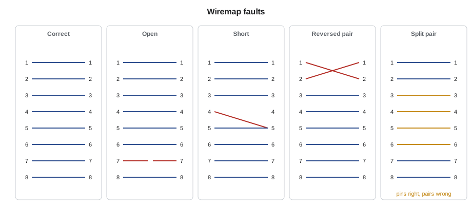
Exam trap: the split pair. A simple continuity tester shows every pin connected to the right pin and reports a pass, because the split pair connects pins correctly but uses the wrong twisted pairs. Only a tester that measures crosstalk, or a wiremap tester that checks pairing, finds it. A question asking which fault a continuity tester cannot find has this as its answer.
Testing tiers
LVT-130 lessons 9 and 10 distinguished three tiers of testing, and exams test the distinction.
| Tier | What it shows | Accepted for warranty? |
|---|---|---|
| Verification | Continuity and wiremap; sometimes length | No |
| Qualification | Whether a link supports a given network application | No |
| Certification | Whether a link meets every limit of a category standard | Yes |
Certification needs a field tester that meets the accuracy level the category demands. TIA-1152-A defines the levels; Category 6A links need level IIIe or better. The tester must be calibrated, have current software and limit tables, use the right adapters for the configuration being tested (permanent link or channel) and have its reference set as the maker requires before the day's testing.
The parameters a certification test measures include wiremap, length, insertion loss, near-end crosstalk (NEXT) and its power sum (PSNEXT), attenuation-to-crosstalk ratio at the far end (ACRF) and its power sum, return loss, propagation delay, delay skew and DC resistance unbalance. A result is a pass, a fail, or a marginal result within the tester's accuracy, often shown with an asterisk. Whether a marginal pass is accepted depends on the specification and the manufacturer's warranty rules; many treat it as a pass, some require it to be investigated.
Length is calculated from the time a signal takes to travel down the cable and back, using the cable's nominal velocity of propagation (NVP), the speed as a fraction of the speed of light. If the tester's NVP setting is wrong, the length reading is wrong by the same proportion, which can turn a 92 m link into an apparent 87 m pass or the reverse.
Worked problem
A length reading with the wrong NVP
A tester set to an NVP of 0.69 reports a link as 88.0 m. The cable's data sheet gives an NVP of 0.66. What is the actual length?
Show solution
- The tester measured a round-trip time and multiplied by 0.69 × c ÷ 2.
- The real length uses 0.66 instead, so it is shorter in proportion: 88.0 × 0.66 ÷ 0.69.
- 88.0 × 0.957 = 84.2 m.
Answer: About 84.2 m. Setting the right NVP matters most on links near the 90 m limit, where a few percent decides pass or fail.
# Name a wiremap fault from the far-end pin each near-end pin reaches (None = open)
PAIRS = [(1, 2), (3, 6), (4, 5), (7, 8)]

def classify(far):
    faults = []
    opens = [p for p in range(1, 9) if far[p] is None]
    if opens:
        faults.append("open on pin " + ",".join(map(str, opens)))
    seen = {}
    for p in range(1, 9):
        if far[p] is not None:
            seen.setdefault(far[p], []).append(p)
    for q, ps in seen.items():
        if len(ps) > 1:
            faults.append("short between pins " + ",".join(map(str, ps)))
    for a, b in PAIRS:
        if far[a] == b and far[b] == a:
            faults.append(f"reversed pair {a}-{b}")
    if all(far[p] == p for p in range(1, 9)):
        return "correct (pins only: a split pair looks the same)"
    if not faults:
        faults.append("crossed or transposed pairs")
    return "; ".join(faults)

straight = {p: p for p in range(1, 9)}
tests = {
    "link A": straight,
    "link B": {**straight, 7: None},
    "link C": {**straight, 1: 2, 2: 1},
    "link D": {**straight, 4: 5, 5: 5},
    "link E": {1: 3, 2: 6, 3: 1, 6: 2, 4: 4, 5: 5, 7: 7, 8: 8},
    "link F (split pair)": straight,
}
for name, far in tests.items():
    print(f"{name:20s} {classify(far)}")

# length correction for a wrong NVP setting
reported, nvp_set, nvp_true = 88.0, 0.69, 0.66
print(f"Reported {reported} m at NVP {nvp_set}: actual {reported * nvp_true / nvp_set:.1f} m at NVP {nvp_true}")link A correct (pins only: a split pair looks the same) link B open on pin 7 link C reversed pair 1-2 link D short between pins 4,5 link E crossed or transposed pairs link F (split pair) correct (pins only: a split pair looks the same) Reported 88.0 m at NVP 0.69: actual 84.2 m at NVP 0.66
The code classifies a wiremap from the far-end pin each near-end pin connects to, which is what the tester's wiremap screen shows in diagram form, and then corrects a length for a wrong NVP. Link E is the classic crossed pairs result, a T568A jack at one end and a T568B jack at the other. The last line of the table makes the split pair point in a different way: a split pair has exactly the same pin-to-pin map as a correct link, so a classifier that sees only pins reports it as correct. That is precisely the limit of a continuity tester, and precisely why certification measures crosstalk. Maya uses the code to drill the fault types until she can name each one at a glance, which is what the practical exam asks when a seeded fault appears in a test link.
Troubleshooting
LVT-130 lesson 11 covered fault finding, and exam questions usually give a result and ask for the most likely cause.
| Result | Most likely cause | Fix |
|---|---|---|
| NEXT fails at one end | Too much untwist, or a poor termination at that end | Re-terminate that end |
| Return loss fails near one end | Kinked or crushed cable, or a poor termination near the end | Inspect the first few meters and the termination |
| Insertion loss fails, length near limit | Link too long, or hot ceiling space raising loss | Reroute or shorten; check temperature |
| Fails with channel adapters, passes as permanent link | Bad patch cord | Replace the cord |
| Split pair | Termination using the wrong pairs | Re-terminate to the scheme |
| Intermittent fault | Damaged conductor, often at a staple or tight tie | Use the tester's fault location to find the distance |
The tester's diagnostic plots, which LVT-130 called time-domain crosstalk and time-domain reflection, show where along the link a problem occurs. A crosstalk peak at 0.4 m means the termination at the near end; a reflection at 37 m means something along the cable at that distance, often a kink, a crushed section or a tight cable tie.
Records and warranty
Every certified link has a saved result with a name that matches its TIA-606 identifier. The results are exported in the tester's native format for the manufacturer's warranty application, and the warranty is issued only when every link in the installation passes. LVT-130 lesson 12 showed the cross-check Cobalt Line runs before submitting: every identifier in the port map has exactly one saved passing result, and every saved result belongs to an identifier in the port map. That cross-check found two errors on the Kellerman floor, and it is the kind of process question that appears on the Technician exam.
Testing setup, step by step
A good result depends on a good setup, and exam questions on testing often ask what the technician should do before the first test. Cobalt Line's setup routine, from LVT-130 lesson 10, is worth memorizing in order.
- Check the tester's calibration date and software version, and update the limit tables if needed.
- Select the right test limit for the job, such as the TIA Category 6A permanent link limit.
- Select the cable type, which sets the NVP, or enter the NVP from the cable's data sheet.
- Fit the right adapters for the configuration: permanent link adapters or channel adapters, with their tips in good condition.
- Set the reference with the adapters the maker specifies, at the start of each day and when the adapters change.
- Set up the project and the naming so that each saved result takes the link's identifier.
- Test a known-good link first, to confirm the setup before testing the job.
Each step corresponds to a common exam distractor: an old limit table, the wrong NVP, channel adapters used for a permanent link test, a reference set with different adapters, or results saved under automatic names that later have to be matched by hand.
Re-terminating versus re-pulling
When a link fails, the cheapest fix is to re-terminate the end that the diagnostics point to. Re-terminating takes minutes and costs a jack; re-pulling takes hours and may disturb other cables. But re-termination only fixes termination faults. A link that fails insertion loss because it is too long, or return loss because of a kink in the middle, will fail again however many times it is re-terminated, and every re-termination uses up some of the slack. The diagnostic plot decides: a fault at the end means re-terminate, a fault along the cable means repair or replace the cable. Exam questions that ask for the most efficient correct action are testing this judgment.
Records reviewers look for
A test report reviewer, whether the client's consultant or the manufacturer's warranty desk, checks a few things quickly: that every result shows the right limit and cable type, that the tester's calibration was current on the test dates, that results carry the right identifiers, and that there are no duplicates or gaps. A report that fails these checks is returned, and the job's completion waits until it is fixed.
Common mistakes
MistakeMultiplying the single-cable tension limit by the number of cables in a pull.
InsteadUse the maker's bundle figure and plan for the worst-loaded cable.
MistakeBending cable sharply behind the faceplate.
InsteadThe installed bend radius applies right up to the termination.
MistakeMixing T568A and T568B in one installation.
InsteadUse one scheme throughout, as specified.
MistakeAccepting a continuity test as proof of a good link.
InsteadOnly certification checks crosstalk and other parameters.
MistakeTesting with the wrong NVP or an old limit table.
InsteadSet the cable's NVP and keep the tester's software and limits current.
Summary and key terms
- Pulling: about 25 lbf per cable, bend radius 4 × diameter installed and 8 × while pulling, supports every 5 ft.
- Terminating: untwist 0.5 in or less, one wiring scheme throughout, the maker's tool.
- T568A and T568B swap the orange and green pairs; a split pair passes continuity but fails crosstalk.
- Verification, qualification and certification are different tiers; only certification supports a warranty.
- Certification needs the right accuracy level, adapters, reference and NVP.
- Diagnostic plots locate faults by distance; records must match the port map exactly.
- Split pair
- A wiring fault that keeps pin continuity but splits signal pairs across different twisted pairs.
- NVP
- Nominal velocity of propagation: signal speed in the cable as a fraction of the speed of light.
- NEXT
- Near-end crosstalk: signal coupled from one pair to another at the same end.
- Return loss
- A measure of signal reflected back toward the source by impedance changes.
- Accuracy level
- The tester performance class defined in TIA-1152-A, such as IIIe for Category 6A.
Practice problems
Work each problem on paper first, then reveal the answer to check.
Which wiremap fault does a simple continuity tester miss?
Show answer
A split pair.
Which pairs swap between T568A and T568B?
Show answer
The orange and green pairs.
Which test tier is accepted for a manufacturer warranty?
Show answer
Certification.
A crosstalk peak appears at 0.3 m on a time-domain plot. Where is the fault?
Show answer
At the near-end termination.
Lesson quiz · 5 questions
Score 60% or more to complete this lesson.
Create a free account to save your progress, take quizzes and earn a certificate.