
IRW-120 · Lesson 9 of 12 · 26 min
Load charts and lift planning
▶ Video coming soon A video version of this lesson is on the way.
The November 5 rigging night was the one the apprentices had been told to bring calculators to. Dwayne handed out copies of a load chart, and Carla handed out the erection drawings for Ashcroft's east bay. "Pick a piece," she said, "find its weight, find where the crane will be, find the radius, and tell me if Dwayne can lift it. Then tell me how sure you are." Reading a load chart is the operator's job, and the lift plan is the lift director's. Ironworkers who understand both make better plans, catch mistakes and know why the crane sometimes has to move before a piece can be set.
What a load chart is
A load chart is the maker's table of a crane's rated capacities for each configuration it can be set up in. It is specific to the make, model and serial number of the crane, and to how it is set up: boom length, outrigger position, counterweight, quadrant and any attachments such as a jib. The chart must be in the cab, readable from the operator's position. A chart from another crane, an old chart or a copy with missing pages is not a chart.
A typical hydraulic crane chart has a main table of capacities by radius and boom length, notes that set out the conditions for using it, tables for the jib and for working on rubber, a range diagram showing the hook height at each boom length and radius, and tables of deductions and of line pull per part of line. The notes matter as much as the numbers. They say, for example, whether the capacities include the hook block, whether a stowed jib must be deducted, whether the capacities above a bold line are limited by structural strength, and how level the crane must be.
Radius, boom length and boom angle
The load radius is the horizontal distance from the crane's center of rotation to the center of the hook, with the load hanging. It is not the distance from the outrigger or from the front of the crane. The radius used must be the loaded radius: a boom deflects under load, and on a long boom the hook moves outward as the load comes on, sometimes by a meter or more. Operators check the radius with the load moment indicator or by measurement after the load is just clear of the ground.
Boom length and boom angle go together with radius: for a given boom length, a lower boom angle gives a longer radius. Charts are read by radius and boom length. A crane with a telescoping boom may have capacities that also depend on how each section is extended, so the operator uses the extension mode the chart is based on.
Reading the chart
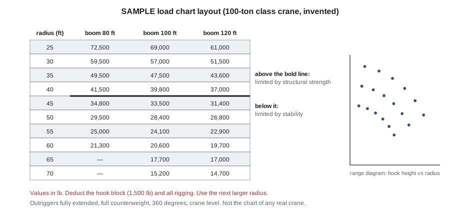
The table below is a SAMPLE chart for a crane like the one at Ashcroft. Values are in pounds. It is invented for this lesson, and no real lift should ever be planned from it.
| Radius (ft) | 80 ft boom (lb) | 100 ft boom (lb) | 120 ft boom (lb) |
|---|---|---|---|
| 25 | 72,500 | 69,000 | 61,000 |
| 30 | 59,500 | 57,000 | 51,500 |
| 35 | 49,500 | 47,500 | 43,600 |
| 40 | 41,500 | 39,800 | 37,000 |
| 45 | 34,800 | 33,500 | 31,400 |
| 50 | 29,500 | 28,400 | 26,800 |
| 55 | 25,000 | 24,100 | 22,900 |
| 60 | 21,300 | 20,600 | 19,700 |
| 65 | — | 17,700 | 17,000 |
| 70 | — | 15,200 | 14,700 |
To read it, find the column for the boom length and the row for the radius, and read the capacity where they meet. If the radius falls between two rows, use the row for the next larger radius, never a value between the two. If the boom length falls between two columns, use the column for the next longer boom, or the operator's chart rules for that crane. Then subtract every deduction the notes require. What is left is the most the crane may lift in that configuration, including everything below the hook.
Capacities near the top of each column are usually limited by structural strength. Lower down, they are limited by stability. Most charts mark the change with a bold line. Above the line, overloading may break something without warning; below it, the crane will start to tip. Neither is acceptable, and the crane's load moment indicator is set to stop the crane before either happens. It is not a tool for finding out how much more the crane will take.
Deductions
The rated capacity on the chart is for the whole crane as configured. Anything the crane carries that is not counted in the chart must be subtracted. The common deductions are:
- The hook block or overhaul ball, unless the chart says its weight is already included.
- All rigging below the hook: slings, shackles, spreader bars, lifting beams, chain hoists and tag lines.
- A jib or extension that is stowed on the boom or erected but not used, as the chart notes say.
- The weight of the auxiliary block or headache ball when the main hoist is used, if it remains reeved.
- Any additional hoist line when the hook is low, on some cranes.
Worked problem
A column pick
Column C-11 at Ashcroft weighs 1,573 lb (lesson 4). It is picked with a shackle and short sling weighing 55 lb. The crane has a 100 ft boom and must set the column at a radius of 65 ft. Using the SAMPLE chart, what fraction of capacity is used?
Show solution
- Load to compare with the chart: 1,573 + 55 + 1,500 (hook block) = 3,128 lb.
- Chart capacity at 65 ft with the 100 ft boom: 17,700 lb.
- Fraction used: 3,128 ÷ 17,700 ≈ 0.18, or about 18 in 100.
Answer: About 18 in 100 of chart. Most columns and beams at Ashcroft were light picks for the crane; the hook block alone was almost half of this load.
The heaviest piece at the worst radius
Lift planning starts with the heaviest pieces and the farthest radii, because those combinations decide where the crane sets up. On Ashcroft, the moment-frame girders at the far end of the building were the heaviest pieces.
Worked problem
Moving the crane for a heavy girder
Girder G-1 weighs 10,600 lb with its connection plates and needs 260 lb of rigging. From the crane's first setup, it would be set at a radius of 70 ft with the 100 ft boom. From the second setup it would be set at 60 ft. What fraction of capacity is used from each setup? Crossbeam treats any lift over 75 in 100 of chart capacity as a critical lift.
Show solution
- Load: 10,600 + 260 + 1,500 = 12,360 lb.
- First setup, 70 ft: 12,360 ÷ 15,200 ≈ 0.81, about 81 in 100.
- Second setup, 60 ft: 12,360 ÷ 20,600 = 0.60, about 60 in 100.
Answer: From the first setup the lift would be a critical lift at about 81 in 100. Carla and Dwayne set the girder from the second setup, at about 58 to 60 in 100, and sequenced the erection so the far-end girders went up after the crane moved.
The check must cover the whole lift, not just the set point. The radius at the pick point, where the piece is lifted from the truck or the shakeout, may be larger than at the set point, and the boom may pass through a quadrant with a lower rating as it swings. The lift plan checks the largest radius and the lowest-rated quadrant the load will pass through.
Line pull and parts of line
The hoist rope is reeved through sheaves in the boom tip and the hook block. Each part of line, each length of rope between the tip and the block, carries a share of the load. The chart gives the maximum line pull for each part. If the load needs more than the parts of line can carry, the block must be reeved with more parts, even if the crane's capacity at that radius is enough.
Worked problem
Enough parts of line?
The SAMPLE chart allows a line pull of 13,000 lb per part. Dwayne's block is reeved with 4 parts. What is the most the hoist line can lift, and is it enough for girder G-1?
Show solution
- Hoist line limit: 13,000 × 4 = 52,000 lb.
- Girder load including block and rigging: 12,360 lb.
Answer: Enough, with a wide margin. On a heavy pick at a short radius, the parts of line can limit a lift before the chart does.
The lift plan
Every lift needs a plan; for routine picks, the plan is the erection sequence, the crane setup drawing and the hooker-on's checks. Heavier or unusual lifts need a written plan. A written lift plan typically includes:
- The load: description, weight with its source, center of gravity and lifting points.
- The rigging: each item, its rated capacity, the hitch and sling angles, and the total rigging weight.
- The crane: make, model, configuration, counterweight, outriggers, and the chart capacities at the pick and set radii and the largest radius in between.
- The fraction of chart capacity used at the worst point.
- The site: crane position, ground bearing and mats, power lines, nearby structures, swing path and exclusion zones.
- Limits: wind, weather and lighting.
- The people: the lift director, operator, rigger, signal person and tag line handlers, and how they communicate.
- The sequence: test lift, hoisting, swing, landing, connection and release.
- Signatures of the lift director and operator, and of the engineer when one is required.
A lift plan is only as good as the information in it. Most failures of planned lifts come from a wrong weight, a wrong radius or a missed deduction, not from bad arithmetic. The plan should say where each figure came from, so anyone checking it can see what was measured, what was calculated and what was assumed.
Before the first pick of the day
Each morning at Ashcroft, Carla and Dwayne compared the day's erection sequence with the crane setup: the heaviest piece of the day, its radius and its fraction of chart, the wind forecast, and anything that had changed on the site overnight, such as a new excavation, a truck parked in the swing path or a change in the order of deliveries. The hooker-on had the day's piece list with weights. Nobody on the gang had to guess.
Range diagrams and hook height
Capacity is only one question; reach is another. The range diagram on the chart shows, for each boom length, how high the boom tip is at each radius. From it the planner finds the hook height available at the set radius, after allowing for the hook block, the rigging, the load's own height and the clearance needed over the steel already in place. A multiple lift or a piece on a long spreader needs more height than a single beam on short chokers (lesson 11). If the hook height is not enough, the boom must be longer or the radius shorter, and either change means checking the capacity again.
When the chart does not fit
Sometimes the crane's configuration on site does not match any part of the chart exactly: an outrigger cannot be fully extended because of an obstruction, the counterweight is reduced for road travel, or the crane is on rubber. Each of these has its own chart or its own rules in the maker's manual, and many cranes have charts for partly extended outriggers. A crane may never use the full-outrigger chart when the outriggers are not fully extended. If the operator is not sure which chart applies, the lift does not happen until the maker or the crane company's engineer says which one does.
Worked problem
A pick at the edge of the chart
A 4,800 lb brace frame with 150 lb of rigging must be set at 70 ft with the 100 ft boom. Using the SAMPLE chart and the 1,500 lb hook block, what fraction of chart is used?
Show solution
- Load: 4,800 + 150 + 1,500 = 6,450 lb.
- Chart at 70 ft: 15,200 lb.
- Fraction: 6,450 ÷ 15,200 ≈ 0.42, or about 42 in 100.
Answer: About 42 in 100 of the chart, even for a light piece, because capacity falls so quickly at long radius.
Carla's last instruction on the chart night was to look at the bottom rows of the chart before the top ones. "Everybody can lift a beam close in. The far corner is where the crane gets small."
Common mistakes
MistakeInterpolating between two radii on the chart.
InsteadUse the next larger radius.
MistakeForgetting the hook block and rigging.
InsteadSubtract every deduction the chart notes require.
MistakeChecking capacity only at the set point.
InsteadCheck the largest radius and the lowest-rated quadrant in the whole swing.
MistakeUsing the unloaded radius.
InsteadUse the loaded radius, allowing for boom deflection.
MistakeTreating the load moment indicator as the limit to work up to.
InsteadPlan within the chart; the indicator is a backup.
MistakeIgnoring parts of line on a heavy, close pick.
InsteadCheck line pull per part as well as chart capacity.
Summary and key terms
- A load chart is specific to the crane and its configuration and must be in the cab.
- Radius is measured from the center of rotation to the center of the hook with the load on.
- Read the chart at the next larger radius, never between rows, and subtract all deductions.
- Upper chart values are limited by structural strength, lower values by stability.
- Plan for the heaviest piece at the largest radius and the lowest-rated quadrant in the swing.
- A lift plan records the load, rigging, crane, capacity used, site, limits, people and sequence, with the source of each figure.
- Load chart
- The maker's table of a crane's rated capacities for each configuration.
- Load radius
- The horizontal distance from the center of rotation to the center of the hook with the load on.
- Deduction
- Weight that must be subtracted from chart capacity, such as the hook block and rigging.
- Parts of line
- The number of rope lengths supporting the hook block.
- Line pull
- The tension the hoist can put in one part of line.
- Lift plan
- A record of how a lift will be made safely, with its load, rigging, crane and procedure.
Practice problems
Work each problem on paper first, then reveal the answer to check.
Using the SAMPLE chart, what is the capacity at 52 ft with the 100 ft boom?
Show answer
Use the 55 ft row: 24,100 lb.
A 6,400 lb load with 200 lb of rigging is set at 60 ft with the 100 ft boom. What fraction of chart is used?
Show answer
(6,400 + 200 + 1,500) ÷ 20,600 = 8,100 ÷ 20,600 ≈ 39 in 100.
Why is the loaded radius used?
Show answer
The boom deflects under load and the hook moves outward.
How many parts of line are needed for a 31,000 lb load at 13,000 lb per part?
Show answer
31,000 ÷ 13,000 ≈ 2.4, so at least 3 parts.
What does the bold line on many charts separate?
Show answer
Capacities limited by structural strength from those limited by stability.
Lesson quiz · 5 questions
Score 60% or more to complete this lesson.
Create a free account to save your progress, take quizzes and earn a certificate.