
INS-310 · Lesson 8 of 12 · 23 min
Duct liner and acoustic lining
▶ Video coming soon A video version of this lesson is on the way.
In her second week at Mountview, Priya met duct insulation from the other side. Harcourt's sheet metal shop had delivered the first sections of supply and return duct for the third-floor air handler, already lined inside with 1 in of black-coated glass fiber liner. Before the sections went up, Marcel and Priya walked the stack of duct on the loading dock with Harcourt's foreman, Gord Fennimore, and a flashlight. Most sections were perfect. Three had torn liner where a forklift fork had gone inside, and one had a loose leading edge flapping at the joint. "Air at sixteen hundred feet a minute will peel that off in a week," Marcel said, "and it'll end up in somebody's room." Gord agreed to have the three repaired in the shop and asked Coldstream to fix the loose edge on site.
Duct liner is insulation installed inside a duct, on its inner walls, so that the air flows over it. It absorbs sound traveling along the duct and insulates the duct thermally at the same time. In many shops, liner is installed by the sheet metal contractor as the duct is made, using machines that cut, glue and pin it; in others, and in repairs, insulators install or fix it. Either way, insulators need to understand how it works, how it must be installed, and how to inspect and repair it. This lesson covers liner, its rules, and other ways of controlling noise in ducts. INS-330 covers acoustic insulation on piping and equipment.
Why line a duct?
Fans, air handlers, dampers and fast-moving air make noise, and a sheet metal duct carries that noise along its length like a speaking tube, into every room it serves. Duct liner absorbs some of the sound energy each time the sound waves strike the duct walls, so the noise is lower at the far end. The longer and thicker the lined section, the more sound it absorbs, especially at middle and high frequencies such as fan whine and air rush. Low-frequency rumble is harder to absorb and needs thicker liner, longer runs or purpose-made silencers.
Liner also insulates the duct. A lined duct may need no external wrap in the lined section if the liner's thermal resistance meets the specification's duct insulation schedule, and on cold ducts the metal is warmer on the outside than an unlined duct would be. Specifications usually say which sections are lined and whether the liner counts as the duct's thermal insulation.
Liner materials
- Glass fiber duct liner is the most common, made to ASTM C1071, which covers fibrous glass liner in flexible rolls (Type I) and rigid boards (Type II). Its airstream face is coated or covered with a facing that resists erosion by the air and is often treated to resist the growth of mold and bacteria. It comes in thicknesses such as 1/2, 1, 1 1/2 and 2 in.
- Mineral wool liner is used where higher temperatures or other properties are needed.
- Closed-cell elastomeric and foam liners are used where fiber in the airstream is not wanted, and in some cleanable or wet-area applications. They absorb less sound than fibrous liner of the same thickness.
- Double-wall duct has an inner perforated metal liner with insulation sandwiched between it and the outer duct wall. The air touches only metal, which is cleanable and very resistant to erosion, while the insulation behind the perforations absorbs sound. It is used in hospitals, laboratories and high-velocity systems.
Duct liner and its adhesive, like external coverings, must meet the flame-spread rating of 25 and smoke rating of 50 that lesson 7 described.
Where liner is not used
Liner is not right everywhere. Fibrous liner can collect dust and, if it gets wet, grow mold, so many specifications keep it out of ducts that can get wet, such as those just downstream of cooling coils and humidifiers, and out of outdoor-air intakes where rain or snow can enter.
Health-care ventilation standards also restrict it. In the US, ASHRAE/ASHE Standard 170 for ventilation of health care facilities, which the FGI Guidelines adopt, limits where internal duct lining may be used in hospital systems, especially downstream of the final filters serving sensitive areas. Mountview's engineer allowed liner only in the sections next to the air handlers, before the final filters, and used double-wall perforated duct and sound attenuators elsewhere.
Always check the specification for where liner may and may not go before repairing or adding any.
How liner is installed
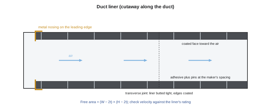
Whether it is done in the sheet metal shop or in the field, liner installation follows the liner maker's instructions and the duct construction standard the specification names, such as the SMACNA HVAC duct construction standards. The key points are:
- Orientation. The coated or marked airstream face goes toward the air. Installed backwards, the uncoated side erodes.
- Adhesive. The liner is bonded to the duct wall with an adhesive meeting ASTM C916, the standard for duct liner adhesives, applied over at least about 90 in 100 of the metal surface, as makers typically require. Adhesive alone is not enough on most ducts; it holds the liner flat between fasteners.
- Mechanical fasteners. Pins, either welded or adhesive-based with washers, or impact-driven fasteners, hold the liner. They are placed close to the leading and trailing edges of each piece and across the faces at a spacing that gets closer as the air velocity rises. Makers' tables give the spacing; at higher velocities the pins may be as close as about 6 in along their rows. Fasteners must not compress the liner more than the maker allows, and must be flush so they do not stick into the airstream.
- Joints and edges. Pieces are butted tightly at their joints with no gaps. Cut edges facing the airstream, called leading edges, are coated with the maker's edge coating, and at high velocities, at the fan discharge and wherever lined duct follows unlined duct, they are protected by metal nosing: a sheet metal channel that covers the edge so the air cannot get under it. Transverse joints between duct sections have their liner edges coated.
- Velocity limit. Each liner has a maximum air velocity rating, tested by ASTM C1071's erosion test. One common coated glass fiber liner, for example, is rated at about 6,000 fpm and calls for metal nosing on leading edges above about 4,000 fpm. Check the rating of the product actually installed against the design velocity.
Checking the velocity
The velocity of the air in a lined duct depends on the airflow and on the free area inside the liner, which is smaller than the duct's nominal size by twice the liner thickness each way.
Worked problem
Is the liner rated for the air speed?
A lined supply duct is 36 × 18 in with 1 in liner and carries 5,000 cfm. The liner is rated to 6,000 fpm, with nosing needed above about 4,000 fpm. What is the air velocity, and is the liner suitable?
Show solution
- Free inside size = (36 − 2 × 1) × (18 − 2 × 1) = 34 × 16 in.
- Free area = 34 × 16 = 544 in² = 544 ÷ 144 = 3.78 ft².
- Velocity = 5,000 ÷ 3.78 = 1,323 fpm.
- That is well under the 6,000 fpm rating and under the 4,000 fpm nosing threshold, so the liner is suitable with coated leading edges; nosing is still needed at the fan discharge and where lined duct follows unlined duct.
Answer: About 1,320 fpm, well within the liner's rating.
Lining a duct also reduces its free area, so a duct sized for unlined airflow must be made larger when it is lined, or the air moves faster and the fan works harder. That is the duct designer's job, but an insulator who notices liner added to a duct that was drawn unlined should raise it.
Inspecting and repairing liner
Liner is inspected before the duct is installed and again before it is closed in. Look for:
- Tears, gouges and crushed areas on the airstream face.
- Loose or lifting edges, especially leading edges, and delamination where the liner has come away from the metal.
- Missing or loose fasteners, or fasteners standing proud into the airstream.
- Gaps at joints between pieces and at transverse joints between sections.
- Wet, stained or dirty liner. Liner that has been wet should be replaced, not dried and left, because mold can grow in it.
Small surface damage is repaired by coating the area with the maker's repair coating. Larger damage is cut out with a straight-sided cut back to sound liner, and a new piece of the same product is fitted, bonded with full adhesive, pinned and edge-coated, with tight butt joints. A loose leading edge is re-glued, pinned close to the edge and coated, and, if the specification or the velocity calls for it, fitted with a nosing. Damaged sections should be repaired before installation wherever possible; repairs inside a hung duct are slow and are often done through access doors.
Worked problem
Adhesive for a lined section
A lined section of the return duct is 26 ft long with an inside perimeter at the metal of 9 ft. The liner adhesive's data sheet gives a coverage of about 200 ft² per gallon at the required full coverage (a sample figure; use the actual product's data). How much liner and adhesive does the section take?
Show solution
- Liner area = 9 × 26 = 234 ft², plus waste.
- Adhesive = 234 ÷ 200 = 1.2 gal, so a 2 gal pail or two 1 gal cans, with a little left for repairs.
Answer: About 234 ft² of liner and 2 gal of adhesive.
Other ways to control duct noise
Liner is one of several tools. Others that insulators meet are:
- Sound attenuators (silencers): factory-made duct sections with absorptive baffles, installed by the sheet metal contractor where a lot of noise reduction is needed in a short length.
- Double-wall perforated duct, described above, which gives absorption with a metal airstream surface.
- External acoustic lagging: a heavy, limp barrier layer, such as mass-loaded vinyl, over a layer of fibrous insulation on the outside of a duct, which reduces noise breaking out through the duct walls into a room. Wrap alone does little for break-out noise; mass is what stops it. INS-330 covers lagging in detail.
- Flexible connectors at fans, which stop vibration traveling into the duct. These are not insulated over rigidly; any covering must stay flexible.
The sound performance of a material is described by its absorption coefficients at different frequencies, often summarized as a noise reduction coefficient (NRC), a single number between 0 and about 1. Glass fiber liner of 1 in typically has an NRC around 0.7, and thicker liner more, while a bare sheet metal duct wall absorbs almost nothing. These figures are typical; makers publish tested values.
The loose edge
On the loading dock, Priya fixed the loose leading edge herself under Marcel's eye. She brushed the dust out from under the liner, applied fresh adhesive to the metal and the liner back, pressed the edge down, added two pins within 3 in of the edge with the welder set for the light-gauge duct, and coated the cut edge with the maker's edge coating. Because this section was at the fan discharge, Gord's crew added a sheet metal nosing over the edge before the duct went up. Three days later, when the air handler ran for its first test, Marcel and Priya stood at the first access door with a flashlight. The edge had not moved.
Liner and the duct's thermal insulation
Where a lined section also needs thermal insulation, the specification decides whether the liner alone is enough. A 1 in glass fiber liner typically has a thermal resistance of roughly R-4, which may meet the requirement for some locations and not others. Where it is not enough, external wrap is added over the lined section, and the two must not leave a gap where the liner ends and the unlined duct begins: the external wrap is usually run past the end of the liner by a short distance so the change from lined to wrapped duct is fully covered. On cold ducts, condensation can form on the outside of a lined duct if the liner is too thin for the space's dew point, so the external vapor retarder rules of lesson 7 still apply wherever the duct's outer surface could fall below the dew point.
Common mistakes
MistakeInstalling liner with the coated face against the metal.
InsteadThe coated or marked face goes toward the air.
MistakeRelying on adhesive alone.
InsteadUse full adhesive coverage plus fasteners at the maker's spacing.
MistakeLeaving leading edges uncoated or un-nosed at high velocity, at fan discharges and after unlined duct.
InsteadCoat every leading edge and add metal nosing where required.
MistakeDrying wet liner and leaving it in place.
InsteadReplace liner that has been wet.
MistakeAdding liner in hospital systems or near coils without checking.
InsteadCheck the specification and health-care standards for where liner is allowed.
Summary and key terms
- Duct liner absorbs sound along the duct and insulates it; it is usually installed in the sheet metal shop.
- Glass fiber liner is made to ASTM C1071 and bonded with ASTM C916 adhesive; liners must meet the 25/50 fire ratings.
- Install with the airstream face to the air, full adhesive, fasteners at the maker's spacing, tight joints and coated or nosed leading edges.
- Check air velocity against the liner's rating using the free area inside the liner.
- Liner is restricted near wet surfaces, in outdoor-air intakes and in parts of health-care systems.
- Repair damage by cutting back to sound liner; replace wet liner; use attenuators, double-wall duct and lagging for other noise problems.
- Duct liner
- Insulation installed on the inside walls of a duct to absorb sound and insulate.
- Airstream surface
- The coated face of a liner that faces the moving air.
- Leading edge
- An edge of liner that faces into the oncoming air.
- Metal nosing
- A sheet metal channel that covers a liner leading edge.
- Double-wall duct
- Duct with a perforated inner metal wall and insulation between it and the outer wall.
- Sound attenuator
- A factory-made duct section with absorptive baffles that reduces noise.
- Noise reduction coefficient
- A single number that summarizes how much sound a material absorbs.
- Break-out noise
- Noise passing out through the walls of a duct into the surrounding space.
Practice problems
Work each problem on paper first, then reveal the answer to check.
A duct is 24 × 12 in with 1 in liner and carries 1,600 cfm. What is the velocity?
Show answer
Free area = 22 × 10 = 220 in² = 1.53 ft²; 1,600 ÷ 1.53 = 1,047 fpm.
Which way does the coated face of liner go?
Show answer
Toward the air.
Where is metal nosing needed?
Show answer
On leading edges at high velocity, at fan discharges and where lined duct follows unlined duct, or as the maker says.
What should be done with liner that got wet?
Show answer
Replace it.
Why does external wrap do little for break-out noise?
Show answer
Stopping break-out noise needs mass, such as a heavy barrier layer; wrap is light.
Lesson quiz · 5 questions
Score 60% or more to complete this lesson.
Create a free account to save your progress, take quizzes and earn a certificate.