
INS-310 · Lesson 12 of 12 · 29 min
Case study: insulating a process vessel
▶ Video coming soon A video version of this lesson is on the way.
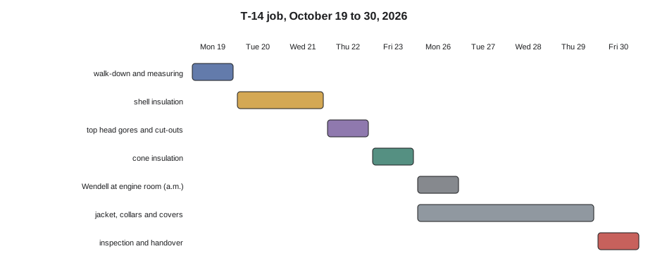
In October 2026, Kellerton Foods installed a new liquid sugar storage tank, tagged T-14, in the sugar room next to its syrup kitchen. Liquid sugar thickens as it cools, so the plant keeps it at about 150 °F with a hot water dimple jacket welded around the lower part of the shell. The tank arrived from its fabricator on October 14, was set on its four legs and piped by the mechanical contractor, and was handed to Coldstream on Monday, October 19, for insulation and jacketing. Wendell Ashby ran the job, with Priya Lam for the whole two weeks and Tomasz Nowicki joining for the jacket. This lesson follows the job from the first walk-down to the handover, using the methods of the whole course.
The vessel
T-14 is a vertical stainless steel vessel, Type 304 throughout, built for food use. Its main features, from the fabricator's drawing and Wendell's own measurements, are:
- A cylindrical shell 96 in in outside diameter and 13 ft tall between tangent lines.
- A 2:1 ellipsoidal top head with a 18 in manway off center, a clean-in-place (CIP) spray nozzle at the center, a vent, and a radar level transmitter.
- A conical bottom sloped at 15 degrees to a central outlet nozzle, so the tank drains completely for cleaning.
- Four legs welded to the shell just above the bottom tangent line.
- A hot water dimple jacket on the lower 6 ft 6 in of the shell, with an inlet and outlet nozzle.
- A nameplate on the shell, a temperature sensor well and a sample valve.
- Fabricator-welded insulation hardware, added at Coldstream's request when Raj Sandhu reviewed the vessel drawing in August: a stainless insulation support ring at the bottom tangent line and eight stainless band clips around the outlet end of the cone, all welded and passivated in the fabricator's shop.
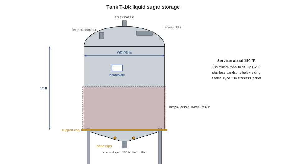
That last item made the job possible. Kellerton's rule, like many food plants', is that nobody welds on a finished stainless food vessel: welding would spoil the passivated surface and could contaminate the product side. Because the support ring and clips were welded in the shop before the vessel was cleaned and passivated, the field crew could hold all the insulation with bands, rings and clips, and no field welding was needed.
The specification
Kellerton's engineer wrote a short specification for the tank, based on the plant's standard for washdown areas:
- Insulation: 2 in of mineral wool, scored board on the shell and semi-rigid board on the heads and cone, meeting ASTM C795 for use on austenitic stainless steel.
- Fastening: stainless bands and seals only; no pins, screws or adhesives in contact with the vessel.
- Jacket: smooth Type 304 stainless, every lap shingled and sealed with the plant's approved sealant, top head gores and center cap, cone jacket lapped to shed water outward, all top edges capped.
- Access: framed opening with a hinged cover at the nameplate; removable cover at the manway; sensor well, sample valve, level transmitter, vent and spray nozzle left accessible.
- Food safety: work to the plant's rules for the sugar room: hair and beard covers, no glass, tool and part counts at the start and end of every shift, all offcuts and dust removed daily.
The ASTM C795 requirement matters. The tank runs at about 150 °F, which INS-220 pointed out is inside the range where austenitic stainless steel can suffer chloride stress corrosion cracking if chlorides are leached from wet insulation onto its surface. ASTM C795 sets limits on the leachable chloride content of insulation for use on austenitic stainless steel, balanced against its sodium silicate content, which inhibits the cracking. Wendell checked that every carton of board delivered carried the maker's C795 statement before it went into the sugar room.
Monday: the walk-down
On Monday, October 19, Wendell, Priya, Lou Brisebois and the plant's sanitation lead walked round T-14. They confirmed the support ring and clips were where the drawing showed them, found that the level transmitter's housing stood only 2 1/4 in above the head and would have to be insulated around carefully so it could still be removed, and agreed that the sample valve's handle should be extended by the mechanical contractor so it would clear the jacket. Priya measured the shell circumference at three heights, the head meridian, the cone slant and the positions of every nozzle, and drew them on the vessel sketch.
Takeoff
Worked problem
Insulation areas and shell bands
The insulated shell is 96 + 2 × 2 = 100 in across and 156 in tall. The top head, measured at the outer surface of the insulation, has an area of about 76.5 ft². The cone, insulated from the shell to a 16 in stop around the outlet, has a slant height of 43 1/2 in. Bands on the shell go at 12 in spacing with the end bands 3 in from each tangent line, each band 3 in longer than the girth. What are the insulation areas, and how many bands and coils of 100 ft are needed for the shell?
Show solution
- Shell area = π × 100 × 156 = 49,009 in² = 340.3 ft².
- Cone area (a frustum) = π × (50 + 8) × 43.5 = 7,926 in² = 55.0 ft².
- Total = 340.3 + 76.5 + 55.0 = 471.8 ft², about 519 ft² with 1 in 10 waste.
- Shell bands: (156 − 6) ÷ 12 = 12.5, so 13 spaces and 14 bands.
- Band length = π × 100 + 3 = 314.2 + 3 = 317.2 in = 26.4 ft; total = 14 × 26.4 = 370.0 ft; coils = 370 ÷ 100 = 3.7, so 4 coils.
Answer: About 472 ft² of insulation (519 ft² with waste) and 14 shell bands from 4 coils.
Tuesday and Wednesday: the shell
The shell went on first, from the bottom up, because the bottom course rests on the support ring. Priya cut the scored board to the measured height of each course, with the grooves toward the vessel, and folded each board round the shell; Wendell followed with bands, a temporary band first at each course and then the permanent bands at their marked spacing. The vertical joints of each course were offset by half a board from the course below, as lesson 1 requires. Over the dimple jacket, which stands about 3/8 in proud of the shell, the board was fitted tight to the jacket and the step at its top edge was filled with a strip of board so the outer surface ran straight. At the dimple jacket's two nozzles, at the nameplate, at the sensor well and at the sample valve, Priya cut the board neatly around each item and closed the cut edges with tight-fitting pieces, leaving room for the jacket collars to come.
The legs were a question the specification did not answer. At 150 °F, heat lost down four small legs is minor, and insulating them would create crevices that the sanitation lead did not want. Lou agreed to leave the legs bare, with the shell insulation and jacket stopped at each leg and sealed around it.
Thursday: the top head
The top head was laid out as lesson 2 describes. With the insulated girth of 314 in at the base, Wendell chose 24 gores, each just over 13 in wide at the base, and a center cap around the spray nozzle.
Worked problem
Gores for the top head
The head's insulated girth at the base is π × 100 = 314.2 in. There are 24 gores and a center cap 16 in across. The meridian from the base to the cap edge is 53 1/4 in. The girth measured at 12, 24, 36 and 48 in along the meridian was 285.6, 226.0, 156.2 and 82.6 in. What are the gore widths at the base, at each station and at the cap edge?
Show solution
- Base: 314.2 ÷ 24 = 13.1 in.
- Stations: 285.6 ÷ 24 = 11.9 in; 226.0 ÷ 24 = 9.4 in; 156.2 ÷ 24 = 6.5 in; 82.6 ÷ 24 = 3.4 in.
- Cap edge: π × 16 ÷ 24 = 50.3 ÷ 24 = 2.1 in.
- Priya cut a plywood template to these points, joined with a smooth curve, and cut all 24 gores from it.
Answer: Gores about 13 1/8 in at the base, narrowing to about 2 1/8 in at the cap.
The gores were held by stainless bands running from a floating ring around the spray nozzle down to the top shell band, as lesson 3 describes, with one band over the middle of every second gore. At the manway, the fixed insulation was cut back from the manway flange by the stud length plus 1 in so the cover could be unbolted, and the gores on each side were trimmed and closed against the manway neck. The level transmitter, the vent and the spray nozzle each got a neatly cut opening with closed edges, so the transmitter could be lifted out without disturbing the insulation.
Friday: the cone
The cone was the hardest part to reach and the hardest to hold, because its insulation hangs beneath it. Wendell and Priya worked from a low platform under the tank, wearing the hard hats the plant requires and bump caps under the platform. The cone pattern was developed by the radial line method that INS-220 used for jacket cones.
Worked problem
The cone pattern
At the outer surface of the insulation, the cone runs from 100 in across at the shell to a 16 in stop at the outlet, with a slant height of 43 1/2 in. What are the pattern's large and small radii and its total angle? How is it divided?
Show solution
- The difference in radius from shell to outlet = (100 − 16) ÷ 2 = 42 in.
- Large pattern radius R = 50 × 43.5 ÷ 42 = 51.8 in. Small radius r = 8 × 43.5 ÷ 42 = 8.3 in.
- Total angle = 360 × 50 ÷ 51.8 = 347.5 degrees. A shallow cone like this one is nearly a flat disc.
- Divided into 8 pieces of about 43.4 degrees each, so each piece of semi-rigid board is small enough to handle and lies close to the cone.
Answer: R = 51.8 in, r = 8.3 in, about 348 degrees, cut in 8 pieces.
The eight cone pieces were held up by stainless bands running from the fabricator's eight clips near the outlet out to the support ring at the bottom tangent line, one band along each joint between pieces, plus a ring band around the cone halfway out. Because the bottom of the cone is where water from any leak above would end up, Wendell had Priya check every joint by eye and with a straightedge before the jacket went on.
Monday to Thursday: the jacket
On Monday, October 26, Wendell spent the morning at the engine room walk-down described in lesson 6, and Tomasz and Priya started the jacket without him. They followed lesson 10 and INS-220: shell sheets from the bottom up, each horizontal lap shingled over the sheet below and sealed with the plant's sealant, vertical laps turned away from the room's washdown hose points, bands at the same spacing as the insulation bands, and no screws anywhere. Around each leg, nozzle and the sample valve, they fitted two-piece collars of stainless, sealed to the jacket and to the item. The top head jacket used 24 gores matching the insulation gores, with a center cap over the floating ring and a sealed collar at the spray nozzle; the cone jacket lapped outward, each piece over the one nearer the outlet, so water would run off its outer edge rather than into the joints.
The nameplate got the framed opening from lesson 11, with a hinged stainless cover lined with insulation. The manway got a removable two-piece stainless box cover, lined with insulation, that closed over the manway flange and its studs and was held by two quick-release latches. Every top edge was capped and sloped. On Thursday, Priya walked the whole tank with a flashlight and a list, sealing two short gaps in the sealant at the cone laps.
Friday: inspection and handover
On Friday, October 30, Lou, the sanitation lead and Raj inspected the tank with Wendell. The sanitation lead found one item: a gap of about 1/16 in where the jacket collar met one leg, which Priya sealed on the spot. Raj noted that the nameplate cover's hinge pin was carbon steel; Tomasz replaced it with stainless from the van. Wendell then walked Lou's maintenance lead through the access points: how to open the manway cover and set it down without damaging it, how the nameplate cover opens, and that the level transmitter could be lifted out through its opening without touching the insulation. Wendell left a one-page sheet listing the removable covers, the materials used, and the rule from lesson 11: insulation removed for maintenance is reinstated by Coldstream before the permit is closed.
| Task | Estimated crew-hours | Actual crew-hours |
|---|---|---|
| Walk-down, measuring, layout | 8 | 9 |
| Shell insulation and bands | 28 | 27 |
| Top head gores, cap and cut-outs | 16 | 18 |
| Cone insulation | 14 | 15 |
| Shell jacket and collars | 32 | 33 |
| Head and cone jacket | 22 | 25 |
| Nameplate and manway covers | 8 | 8 |
| Daily food-safety cleanup and counts | 8 | 6 |
| Total | 136 | 141 |
The job ran five hours over the estimate, almost all on the top head and cone, where the transmitter and the spray nozzle took longer than planned, partly offset by faster cleanups than expected. Raj added a note to Coldstream's estimating sheet: allow extra time for each instrument on a vessel head.
What the insulation does
Worked problem
Heat saved on T-14
Bare, the tank's 472 ft² of surface at 150 °F in a 68 °F room would lose about 114 Btu/h per ft². Insulated, it loses about 10.5 Btu/h per ft². The tank is kept warm all year, 8,760 hours. How much heat does the insulation save in a year?
Show solution
- Bare loss = 472 × 114 = 53,808 Btu/h.
- Insulated loss = 472 × 10.5 = 4,956 Btu/h.
- Saving = 53,808 − 4,956 = 48,852 Btu/h; yearly = 48,852 × 8,760 = 428,000,000 Btu, about 428 MMBtu.
Answer: About 49,000 Btu/h, or about 430 MMBtu of heat a year.
The heat loss values are typical figures for bare stainless and for this insulation at these temperatures; INS-410 shows the full method. The insulation also keeps the jacket surface at a temperature people can touch, keeps the sugar room cooler, and steadies the tank temperature so the dimple jacket's controls work less. And because of the sealed stainless jacket and the C795 insulation, the stainless shell underneath should stay dry and free of chloride cracking for the life of the tank.
Lessons from T-14
- The most valuable hour on the job was spent in August, when Raj asked the fabricator to weld the support ring and clips in the shop. Ask early for the hardware the insulation will need.
- Read the service conditions for hidden requirements: a stainless tank at 150 °F needs C795 insulation.
- Walk the vessel before cutting anything, with the people who will use it, and fix interferences, such as the sample valve handle, before they are buried.
- Lay out heads and cones from measurements and calculations, and make templates.
- In a food plant, the finish is part of the food safety system: sealed laps, capped edges, no crevices, stainless hardware.
- Hand over the access points to the people who will open them.
Common mistakes
MistakePlanning to weld insulation hardware on a finished stainless food vessel.
InsteadGet the fabricator to weld it in the shop before passivation, or use bands and clamp-on rings.
MistakeUsing ordinary insulation on stainless steel in the chloride cracking range.
InsteadUse insulation that meets ASTM C795 and keep it dry.
MistakeInsulating the cone without checking every joint before jacketing.
InsteadCheck the bottom carefully; it is where leaked water ends up.
MistakeBurying instruments and valves that must be removed or operated.
InsteadCut neat, closed openings and have interferences moved before insulating.
MistakeLeaving without showing the plant how to open the covers.
InsteadHand over every access point in person.
Summary and key terms
- T-14 combined shell, head and cone methods with no field welding, thanks to fabricator-welded ring and clips.
- ASTM C795 insulation protected the stainless shell from chloride stress corrosion cracking at 150 °F.
- The shell was insulated bottom up from the support ring, with staggered scored board and stainless bands.
- The top head used 24 gores and a center cap on bands to a floating ring; the cone used a radial pattern in 8 pieces on bands to clips.
- The stainless jacket was shingled, sealed and capped for washdown, with framed nameplate and removable manway covers.
- Inspection, handover and a cover list closed the job; the insulation saves about 49,000 Btu/h of heat.
- Dimple jacket
- A thin outer shell welded to a vessel in a dimpled pattern, through which heating or cooling fluid flows.
- Clean-in-place
- A system that cleans a vessel inside without taking it apart, usually through spray nozzles.
- Passivation
- A chemical treatment that restores the corrosion-resistant surface of stainless steel.
- ASTM C795
- The standard limiting leachable chlorides in insulation used on austenitic stainless steel.
- Chloride stress corrosion cracking
- Cracking of stressed austenitic stainless steel caused by chlorides, especially when warm and wet.
- Frustum
- A cone with its tip cut off; the shape of a conical bottom insulated to an outlet stop.
- Template
- A pattern cut once and used to mark many identical pieces.
Practice problems
Work each problem on paper first, then reveal the answer to check.
Why was no field welding needed on T-14?
Show answer
The fabricator welded the support ring and band clips in the shop before passivation.
What are the base and cap widths of 24 gores on a head with a 276 in base girth and a 12 in cap?
Show answer
276 ÷ 24 = 11.5 in; π × 12 ÷ 24 = 1.57 in.
A cone runs from 80 in to 12 in with a slant of 36 in. What is R?
Show answer
40 × 36 ÷ 34 = 42.4 in.
Why were the legs left bare?
Show answer
Heat loss down the legs is minor at this temperature, and insulating them would create crevices in a washdown area.
Why does a stainless tank at 150 °F need C795 insulation?
Show answer
It is in the range where wet insulation can leach chlorides that crack austenitic stainless.
Lesson quiz · 5 questions
Score 60% or more to complete this lesson.
Create a free account to save your progress, take quizzes and earn a certificate.