
HSE-321 · Lesson 7 of 12 · 28 min
UPS systems, bypasses and stored energy
The uninterruptible power supply is the heart of the critical power chain and the piece of equipment that most often surprises people who are new to data centers. A UPS is designed so that its output never goes dead. It has more than one input, a battery that cannot be switched off, capacitors that hold charge after shutdown and internal logic that can transfer the load between paths in milliseconds without anyone touching it. Every one of those features protects the load, and every one is a potential hazard for the person who opens the cabinet. DCE-340 Lesson 1 explains UPS topologies from an engineering point of view. This lesson looks at the same equipment from the point of view of the technician who must service it safely.
Operating modes and why they matter
A large double-conversion UPS can operate in several modes, and the mode at the moment of the work decides which parts are energized and how the load will behave if something goes wrong.
| Mode | What feeds the load | What is energized inside the UPS | Safety significance |
|---|---|---|---|
| Normal (double conversion) | Inverter, from rectifier and DC bus | Rectifier input, DC bus, battery, inverter, output, usually bypass input | Everything is live; no internal work |
| Battery operation | Inverter, from battery | DC bus, battery, inverter, output | Load is on limited autonomy; avoid adding risk |
| Eco or high-efficiency mode | Bypass, with inverter ready | Bypass path and inverter both live | Faster transfers; same internal hazards |
| Static bypass | Utility or generator through static switch | Bypass input and static switch; inverter may be off but DC bus live | No battery protection for the load |
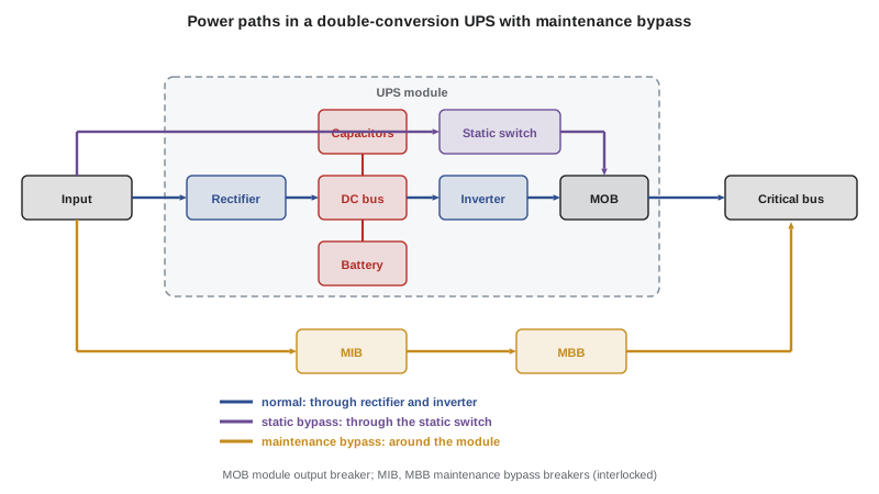
| Maintenance bypass | Wrap-around bypass, outside the UPS module | Module can be isolated, but the bypass cabinet is live | The only mode that allows internal UPS work, after full isolation |
The important point is that no mode makes the whole UPS system dead while the load is running. In maintenance bypass, the load runs through the wrap-around bypass cabinet or switchboard, which is fully energized. The UPS module can then be isolated, but only if every source is opened and locked, and only after stored energy has been released and absence of voltage verified.
Bypass transfers and interlocks
Transferring a UPS to maintenance bypass, and back, is one of the most common and most consequential switching operations in a data center. If it is done in the wrong order, or when the bypass supply is not synchronized with the UPS output, the load can be dropped or two out-of-phase sources can be connected together, causing a fault and possibly an arc flash at the bypass cabinet.
For that reason, UPS systems and their bypass cabinets use interlocks. Common designs include key interchange interlocks, where a key released by one breaker is needed to operate another; solenoid key release units, which release a key only when the UPS confirms that it is in static bypass and synchronized; and electrical interlocks in the UPS control logic. The interlock scheme is designed so that a make-before-break transfer to maintenance bypass can happen only when the two sources are in phase, and so that the module output cannot be closed onto the bypass in an unsafe state.
Interlocks are safety devices, and the rules about them are simple:
- Follow the manufacturer's transfer procedure exactly, as written into the site's switching order, step by step with peer verification.
- If an interlock prevents a step, stop. The interlock is telling you that the system is not in the state the procedure expects.
- Never defeat, bypass or force an interlock, and never use a spare or duplicate key to get around one. Spare keys must be controlled by the switching authority.
- If an interlock appears to be faulty, treat it as an equipment problem for the manufacturer and engineering, not as an obstacle for the crew.
Lesson 8 explains how switching orders are written and executed. For UPS bypass transfers in particular, many sites require the manufacturer's field service engineer to be present or available by phone for the first transfers on a new system, and require the operator to confirm the UPS mode on the front panel at each step.
Backfeed
Backfeed is energy flowing in the opposite direction to normal. In a UPS, the classic case is the inverter or battery energizing the bypass input terminals through the static switch when the upstream supply has been opened. A worker who opens the bypass input breaker upstream and assumes the cables to the UPS are dead could be exposed to voltage from the UPS itself.
UPS product safety standards require backfeed protection, typically a contactor or other isolation device that opens the bypass path when the UPS detects that power is flowing backwards toward the input, and the manufacturer's labels warn of backfeed risk at the input terminals. But backfeed protection is not an isolation device for maintenance. The correct approach is to treat every terminal of the UPS as potentially energized from inside until the UPS is fully shut down, its battery is isolated, its stored energy is released and absence of voltage is verified.
Paralleled UPS systems add another backfeed path: other modules on the same output bus can energize the output terminals of the module being serviced. The module output breaker must be opened and locked, and its outgoing side tested.
Stored energy in capacitors
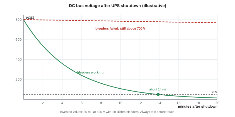
A UPS contains large banks of capacitors. DC bus capacitors smooth the DC link between rectifier and inverter, and AC filter capacitors shape the input and output waveforms. When the UPS is shut down and all sources are opened, these capacitors can hold a lethal charge for some time. Most UPSs include bleeder resistors or discharge circuits, and manufacturers state a minimum waiting time after shutdown before covers may be removed, often shown on a label inside the cabinet. That waiting time must be respected, and absence of voltage must then be verified on the DC bus, because a failed bleeder resistor leaves the capacitors charged.
The energy stored in a capacitor is \(E = \tfrac{1}{2} C V^2\), so it grows with the square of voltage. A capacitor bank discharging through a resistor decays exponentially, with time constant \(\tau = RC\). The time for the voltage to fall from \(V_0\) to a lower value \(V\) is:
The program below uses invented but realistic values for a large UPS to show how much energy is stored and why the manufacturer's waiting time matters.
import math

# Illustrative DC bus capacitor bank in a large UPS (invented values).
C = 0.030        # farads (30 mF total)
V0 = 800.0       # volts on the DC bus at shutdown
R_bleed = 10000  # ohms, built-in bleeder resistors
SAFE = 50.0      # target voltage (V)

energy = 0.5 * C * V0 ** 2
tau = R_bleed * C
t_safe = tau * math.log(V0 / SAFE)
print(f"Stored energy at {V0:.0f} V: {energy/1000:.1f} kJ")
print(f"Time constant RC: {tau:.0f} s")
print(f"Time to fall below {SAFE:.0f} V with bleeders working: {t_safe/60:.1f} min")
for minutes in (1, 5, 10, 15):
    v = V0 * math.exp(-minutes * 60 / tau)
    print(f"  after {minutes:2d} min: {v:6.1f} V")
print("If the bleeders have failed, the voltage barely falls: test before touch.")Stored energy at 800 V: 9.6 kJ Time constant RC: 300 s Time to fall below 50 V with bleeders working: 13.9 min after 1 min: 655.0 V after 5 min: 294.3 V after 10 min: 108.3 V after 15 min: 39.8 V If the bleeders have failed, the voltage barely falls: test before touch.
With working bleeders, the bank in this invented example falls below 50 V in about 14 minutes, so a manufacturer might specify a waiting time of 15 minutes or more. After one minute it is still above 700 V and holds most of its energy. The last line is the key safety point: the waiting time assumes the discharge circuit works. Testing for absence of voltage on the DC bus is what confirms it did.
The battery connection
The battery is connected to the UPS DC bus through a battery breaker or disconnect, often in a separate battery cabinet or a battery room. Opening the battery breaker isolates the battery from the UPS, but the battery itself, and the cables from it to the breaker, remain energized. A typical UPS battery string operates somewhere around 400 to 600 V DC, depending on the design.
# Illustrative UPS battery string voltages (typical per-cell values; designs vary).
designs = {
    "VRLA, 40 x 12 V blocks": (40 * 6, 2.0, 2.27),    # cells, nominal V/cell, float V/cell
    "Lithium iron phosphate, 160 cells": (160, 3.2, 3.4),
    "Lithium NMC, 136 cells": (136, 3.6, 4.0),
}
for name, (cells, nominal, high) in designs.items():
print(f"{name:36s} nominal {cells*nominal:5.0f} V DC, up to about {cells*high:5.0f} V DC")VRLA, 40 x 12 V blocks nominal 480 V DC, up to about 545 V DC Lithium iron phosphate, 160 cells nominal 512 V DC, up to about 544 V DC Lithium NMC, 136 cells nominal 490 V DC, up to about 544 V DC
Whatever the chemistry, the battery is a source that cannot be turned off and that can deliver very high fault currents into a short circuit. Working on battery terminals, interconnecting links or battery cables requires insulated tools, DC-rated PPE and the boundaries from Lesson 5, even when the UPS is completely isolated. Lithium-ion systems add a battery management system and the risk of thermal runaway. HSE-322, Battery Rooms and Lithium-Ion Hazards, covers this in depth.
Modular and hot-swappable UPS designs
Many newer UPS systems are modular: a frame holds several power modules, each of which can be inserted or removed while the frame and the other modules carry the load. Manufacturers design these modules to be replaced live, with shrouded connectors and interlocks that disconnect the module before it can be withdrawn. Hot-swapping a power module according to the manufacturer's instructions is a recognized task, but it is still work in or near an energized frame. The site's risk assessment should cover it, the people doing it should be trained on that model and the task should never extend to reaching into the frame, working on the backplane or defeating module interlocks.
Common UPS failure modes with safety consequences
UPS components wear out, and some failures create hazards for people nearby as well as for the load.
- Capacitor failure. Electrolytic and film capacitors age with heat and time. A failing capacitor can vent or rupture, and in rare cases cause a fault inside the cabinet. Manufacturers recommend replacement intervals, often in the range of five to ten years depending on the component and conditions.
- Fan failure. Cooling fans keep power electronics within temperature limits; fan failures raise internal temperatures and accelerate other failures.
- Loose connections. Heavy currents and thermal cycling loosen connections, causing heating that infrared scans can detect (Lesson 11).
- Battery problems. Failing cells, swelling, leaks or high temperatures in battery cabinets are covered in HSE-322.
- Control failures. A failed control board can cause an unexpected transfer, which is one reason why the operator must confirm the UPS mode at each switching step.
Worked problem
Preparing a UPS module for capacitor replacement
The UPS manufacturer's field service engineer will replace the DC capacitors in UPS module A1 at Cedar Ridge. Module A1 is one of two paralleled modules on the A side, and the A-side load will run on the maintenance bypass during the work. The manufacturer's label inside the cabinet states a waiting time of 15 minutes after shutdown. Outline the stored energy and isolation steps.
Show solution
- Transfer the A-side load to maintenance bypass according to the switching order, confirming the UPS mode and interlock state at each step.
- Isolate module A1: open and lock the rectifier input, static bypass input and module output breakers, so neither the utility, the bypass nor the other module can energize it.
- Open and lock the battery breaker for module A1, noting that the battery and its cables remain energized up to that breaker.
- Shut down the module according to the manufacturer and wait at least the stated 15 minutes for the capacitors to discharge.
- Test for absence of voltage on the AC input and output terminals, the bypass input and the DC bus, using a meter rated for DC at the bus voltage, with live-dead-live verification, before any capacitor is touched.
Answer: Load on maintenance bypass, all four module connections opened and locked, battery breaker opened with the battery side still treated as live, at least 15 minutes of waiting, and absence of voltage verified on every AC and DC point before work begins.
Common mistakes
MistakeBelieving a UPS in static bypass is safe to work inside.
InsteadOnly after transfer to maintenance bypass, full isolation of the module, discharge and testing is internal work permitted.
MistakeUsing a spare key to get past an interlock that blocks a bypass transfer step.
InsteadStop; the interlock is reporting an unsafe state. Never defeat interlocks.
MistakeAssuming the UPS input cables are dead after opening the upstream breaker.
InsteadTreat all UPS terminals as possibly energized by backfeed until the UPS is shut down, isolated and tested.
MistakeRemoving covers as soon as the UPS display goes dark.
InsteadWait at least the manufacturer's stated time and then test the DC bus for absence of voltage.
MistakeTreating the battery as isolated once the battery breaker is open.
InsteadRemember the battery and its cables to the breaker remain energized and can deliver very high fault current.
Summary and key terms
- A UPS is designed so its output never goes dead; it has multiple inputs, a battery, capacitors and automatic transfer logic.
- Only maintenance bypass, followed by full isolation, discharge and testing, allows work inside a UPS module.
- Bypass transfers rely on interlocks that must never be defeated; if an interlock blocks a step, stop.
- Backfeed can energize UPS input terminals from inside; backfeed protection is not a maintenance isolation device.
- Capacitors store \(E = \tfrac{1}{2}CV^2\) and need the manufacturer's waiting time plus a test to confirm discharge.
- Batteries cannot be switched off and remain energized up to the battery breaker; HSE-322 covers battery hazards in depth.
- Static switch
- The electronic switch inside a UPS that transfers the load to the bypass supply.
- Wrap-around bypass
- An external maintenance bypass path that feeds the load while the UPS module is isolated.
- Key interchange interlock
- A mechanical interlock in which a key released by one device is required to operate another.
- Solenoid key release unit
- An interlock that releases a key only when the UPS confirms a safe state, such as synchronized bypass.
- Backfeed protection
- A device in a UPS that prevents energy flowing back into the bypass input when the supply is lost.
- DC bus
- The internal DC link between rectifier, battery and inverter in a double-conversion UPS.
- Bleeder resistor
- A resistor that discharges a capacitor bank after the power is removed.
- Hot-swappable module
- A power module designed to be inserted or removed while the frame remains energized.
Practice problems
Work each problem on paper first, then reveal the answer to check.
Which UPS mode allows work inside the UPS module, and what else is required?
Show answer
Maintenance bypass, followed by full isolation of the module, discharge of stored energy and testing for absence of voltage.
Why are interlocks used between the module output and maintenance bypass breakers?
Show answer
To prevent out-of-phase connections and unsafe transfers that could drop the load or cause a fault.
What should you do if an interlock blocks a step in a bypass transfer?
Show answer
Stop and report; never defeat or bypass the interlock.
What is backfeed at a UPS bypass input?
Show answer
Energy from the UPS inverter or battery reaching the bypass input terminals through the static switch.
Calculate the energy stored in a 20 mF capacitor bank at 700 V.
Show answer
One half of 0.020 times 700 squared, which is 4,900 J or about 4.9 kJ.
Why is testing needed after the manufacturer's waiting time?
Show answer
The waiting time assumes the discharge circuit works; a failed bleeder leaves the capacitors charged.
What voltage range is typical for a UPS battery string?
Show answer
Roughly 400 to 600 V DC, depending on the design.
Does opening the battery breaker make the battery cables dead?
Show answer
No; the battery and its cables to the breaker remain energized.
What limits apply to hot-swapping a UPS power module?
Show answer
Follow the manufacturer's procedure, be trained on the model, cover it in the risk assessment and never reach into the frame or defeat interlocks.
Name two UPS failure modes with safety consequences.
Show answer
Capacitor venting or rupture, fan failure, loose connections, battery problems or control failures.
Lesson quiz · 5 questions
Score 60% or more to complete this lesson.
Create a free account to save your progress, take quizzes and earn a certificate.