
HSE-321 · Lesson 1 of 12 · 36 min
The critical power chain and where hazards concentrate
Electrical safety in a data center starts from the same physics as electrical safety anywhere else. Current through the body injures and kills, an arcing fault releases intense heat, light, pressure and molten metal, and the only reliable protection is to put the equipment into an electrically safe work condition before anyone touches it. HSE-214, Electrical Safety Awareness, and HSE-224, Working On or Near Energized Electrical Systems, teach those fundamentals, and HSE-210, Lockout/Tagout (Control of Hazardous Energy), teaches the lockout process. This course does not repeat them. It applies them to a particular kind of building: the mission-critical facility, where the electrical system is designed never to stop and where that design goal changes how hazards arise and how work must be planned.
This course is the second in the data center sites track. HSE-320, Data Center Safety Essentials, gave every worker an awareness of electrical rooms, approach boundaries, emergency power off buttons and the rule that only qualified persons work on electrical equipment. HSE-321 is written for the people who will be those qualified persons, or who will plan, supervise, permit and audit their work: facility electricians, critical environment technicians, electrical contractors, commissioning agents, facility managers, operations engineers and the safety professionals who support them. HSE-322 covers battery rooms and lithium-ion hazards, and HSE-323 covers fire suppression and liquid cooling hazards. For the engineering of the power systems themselves, the DCE courses go deeper: DCE-310, Data Center Power Distribution, and DCE-340, Backup Power: UPS, Batteries and Generators.
In this first lesson you will trace the critical power chain from the utility to the server, identify where the energy and the hazards concentrate along it and see why redundancy, which protects the service, creates its own electrical hazards for the people who work on it. You will also meet Cedar Ridge Colocation, the invented facility used for examples throughout the course.
Why critical facilities are different
In an office building, a factory or a school, the electrical system serves the building. If an electrician needs to work on a panel, the owner can usually accept a short outage on a weekend. In a data center the relationship is reversed. The building exists to serve the electrical load, and the load is expected to run every second of every year. Customers sign contracts with service levels of 99.99% or better, and some facilities are designed and certified to tiers that require the ability to maintain any component without shutting down the IT equipment. DCE-450 and DCE-340 explain tiers and redundancy in detail.
That expectation shapes the electrical system in three ways that matter for safety. First, there is more of it. A data center has far more switchgear, transformers, uninterruptible power supplies, batteries and distribution equipment per square meter than almost any other commercial building. Second, it is redundant. Most critical loads are fed by two or more independent paths, so there are more sources of energy that can reach any given piece of equipment. Third, it is always on. Equipment is maintained, modified and expanded while the load runs, so electricians routinely work beside, and sometimes on, equipment that is energized and carrying load.
Each of these features is good engineering. Together they produce a workplace where the familiar electrical hazards are present at higher energy levels, in more places and with more pressure to work on equipment without shutting it down. The rest of this course is about meeting that pressure with planning rather than with risk.
The critical power chain
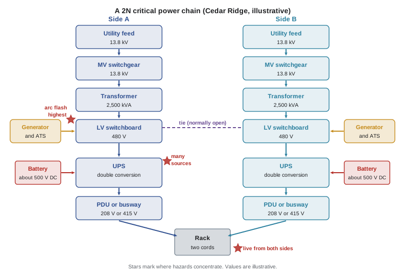
The path that electrical energy takes from the utility to a server is called the power chain. DCE-200 introduces it and DCE-310 explains each element in engineering detail. Here we walk it from the point of view of the person who must work on it, noting what each element does and what hazards it brings.
Utility service and medium-voltage switchgear. Power arrives from the utility at medium voltage, commonly in the range of 4.16 kV to 34.5 kV in the United States (12.47 kV and 13.8 kV are both common), and larger campuses may have their own substation at transmission voltage. Medium-voltage switchgear, ring main units and protective relays distribute this power around the site. Medium-voltage equipment carries the highest shock hazard in the facility and requires specialized qualification, tools and switching procedures.
Transformers. Unit substation transformers step medium voltage down to the facility's main low-voltage level, usually 480 V in the United States (480Y/277 V). A large transformer can supply tens of thousands of amperes into a fault on its secondary side, which is why the low-voltage switchgear just downstream is often the place with the highest arc flash incident energy in the building.
Generators and transfer equipment. Standby generators, usually diesel and increasingly gas-fired or supplemented by other sources, start when utility power fails. Automatic transfer switches (ATS), or paralleling switchgear for multiple generators, move the load from utility to generator and back. These are points where two independent sources meet, so they are central to any isolation plan, and a generator can start automatically while someone is working downstream unless it is properly controlled.
Low-voltage switchgear and switchboards. Main switchboards distribute low-voltage power to UPS systems, mechanical equipment and other loads through large draw-out or fixed circuit breakers. They combine high available fault current with frequent operation, racking of breakers and maintenance, which makes them a focus of arc flash incidents.
Uninterruptible power supplies. A UPS sits between the switchboard and the critical load and keeps the load running through a utility failure until the generators take over. The common large-facility design is the double-conversion UPS, which rectifies incoming AC to DC, keeps a battery connected to the DC bus and inverts DC back to clean AC for the load. A static bypass lets the load ride on raw utility power if the inverter fails, and a maintenance bypass lets technicians isolate the UPS completely while the load continues on another path. Lesson 7 is devoted to UPS hazards: multiple inputs, stored energy in capacitors and batteries, and backfeed.
Batteries and energy storage. The UPS battery, valve-regulated lead-acid in many older sites and lithium-ion in most new ones, is a large DC source that cannot be switched off. It stays energized even when the UPS is shut down, and it can deliver very high fault currents. HSE-322 covers battery rooms in depth.
Power distribution units, remote power panels and busway. Downstream of the UPS, power distribution units (PDUs), which often contain a transformer stepping 480 V down to 208Y/120 V, and remote power panels (RPPs) feed branch circuits to the racks. Many newer halls use overhead busway with plug-in tap-off units instead. In high-density AI halls, distribution at 415Y/240 V is increasingly common because it delivers more power per circuit.
Static transfer switches and rack power. A static transfer switch (STS) can switch a load between two UPS sources in a few milliseconds, so that single-corded equipment can still benefit from two paths. Inside the rack, rack PDUs (power strips) distribute power to the servers, and in modern AI racks power shelves convert AC to DC, commonly to about 48 to 54 V DC on a busbar at the back of the rack.
Where the energy concentrates
Not every point in the chain is equally dangerous. Two quantities tell you most of what you need to know about the electrical hazard at a given piece of equipment: the voltage, which drives the shock hazard and decides which approach boundaries apply, and the available fault current together with the time the protective device takes to clear a fault, which drive the arc flash incident energy. HSE-224 explains the physics; here is how they play out along the chain.
Shock hazard is highest at medium voltage and decreases as voltage is stepped down, but it never disappears. Branch circuits at 120 V can kill, and the DC busbars at the back of an AI rack, although low in voltage, can deliver thousands of amperes into a short circuit, causing severe burns from molten metal and arcing even when the shock hazard is small.
Arc flash hazard does not follow voltage in the same way. The highest incident energies in a data center are usually found on the low-voltage side of large transformers, in the main switchgear and switchboards, because the available fault current is very high and the upstream protective device, which may be on the medium-voltage side, can take a relatively long time to clear a fault on the low-voltage bus. Values high enough that no arc-rated PPE is adequate, and energized work must not be done at all, are not unusual at these locations. Further downstream, in PDUs and RPPs, impedance limits the fault current and faster breakers clear faults more quickly, so incident energies are usually lower, although not always low enough to ignore.
| Location | Typical voltage (US) | Shock hazard | Arc flash hazard (typical) | Special issues |
|---|---|---|---|---|
| Medium-voltage switchgear | 12.47 kV or 13.8 kV | Very high | High; depends on relay settings | Specialized switching; induced voltage; MV-rated tools |
| Transformer secondary and main switchgear | 480 V | High | Often the highest in the facility | Very high fault current; slow upstream clearing |
| Generator and transfer switch | 480 V | High | High | Second source; automatic start |
| UPS | 480 V AC in and out; about 500 V DC battery | High | Moderate to high | Multiple inputs; capacitors; DC bus; backfeed |
| Battery cabinet or room | About 500 V DC (string) | High | Moderate to high; DC arcs | Cannot be switched off; chemical hazards |
| PDU and RPP | 480 V in; 208 V or 415 V out | High | Lower, but not negligible | Dual-corded loads; many branch circuits |
| Busway and tap-off units | 208 V or 415 V | High | Lower to moderate | Live plug-in; overhead work |
| Rack power shelf and busbar | About 48 to 54 V DC | Low | High current, burn hazard | Thousands of amperes available |
The table makes an important point that surprises some newcomers: the most dangerous arc flash locations are often not the highest-voltage ones. Workers who treat medium-voltage switchgear with great respect may be more casual about a 600 V or 480 V switchboard, when the switchboard can have much higher incident energy. The arc flash label, covered in Lesson 4, is the only reliable guide.
Estimating fault current at a transformer
You will not perform arc flash studies in this course; that is engineering work, covered in DCE-310, done to IEEE 1584 by qualified engineers. But a quick estimate of the fault current a transformer can deliver helps explain why the low-voltage switchgear is so dangerous. The maximum symmetrical fault current at the secondary terminals of a transformer, assuming an infinitely strong utility, is the full-load current divided by the per-unit impedance of the transformer.
Here \(S\) is the transformer rating in volt-amperes, \(V_{LL}\) is the secondary line-to-line voltage and \(Z_{pu}\) is the transformer impedance as a fraction, for example 0.0575 for 5.75%. The real fault current is a little lower because the utility and cables add impedance, and motors and generators can add to it. The short program below compares a few typical data center transformers at both North American low voltages.
import math

# Illustrative: maximum symmetrical fault current at a transformer secondary,
# assuming an infinite utility source (a conservative, simplified estimate).
def fault_current(kva, volts, z_percent):
    full_load = kva * 1000 / (math.sqrt(3) * volts)
    return full_load, full_load / (z_percent / 100)

units = [(1500, 5.75), (2500, 5.75), (3000, 6.5)]
for volts in (600, 480):
    print(f"Secondary voltage {volts} V")
    for kva, z in units:
        fla, isc = fault_current(kva, volts, z)
        print(f"  {kva:5d} kVA, Z = {z:4.2f}%: full load {fla:6.0f} A, "
f"fault current about {isc/1000:5.1f} kA")Secondary voltage 600 V 1500 kVA, Z = 5.75%: full load 1443 A, fault current about 25.1 kA 2500 kVA, Z = 5.75%: full load 2406 A, fault current about 41.8 kA 3000 kVA, Z = 6.50%: full load 2887 A, fault current about 44.4 kA Secondary voltage 480 V 1500 kVA, Z = 5.75%: full load 1804 A, fault current about 31.4 kA 2500 kVA, Z = 5.75%: full load 3007 A, fault current about 52.3 kA 3000 kVA, Z = 6.50%: full load 3608 A, fault current about 55.5 kA
A single 2,500 kVA transformer can deliver roughly 40 kA into a fault at 600 V and about 52 kA at 480 V, before any contribution from generators or motors. Large data centers often have many such transformers. That available current is why the arc flash study, the protective device settings and the use of energy-reducing maintenance switching, covered in Lesson 4, matter so much at the main switchgear.
How redundancy creates hazards
Redundancy means having more than one way to deliver power to the load. Common arrangements, explained in DCE-340, include N+1, where one spare component backs up a group, and 2N, where two complete independent systems each can carry the whole load. Dual-corded IT equipment draws power from both an A path and a B path, so that either can fail or be maintained without the server losing power.
From a reliability point of view, redundancy is what lets a facility stay up while maintenance happens. From a safety point of view, it means that a piece of equipment may be connected to more than one source, and that turning off one source does not make it safe. Consider some common examples.
- A UPS module may have a rectifier input, a separate static bypass input, a maintenance bypass, a battery and an output that is tied to other modules or to the load bus. Opening the rectifier input breaker leaves at least four other possible sources.
- A static transfer switch has two inputs from two different UPS systems. Isolating one input leaves the STS energized from the other.
- A dual-corded rack is energized from both the A and B PDUs. Unplugging the A cord leaves the B cord live, and the power shelf may also have batteries.
- A main-tie-main switchboard can be energized from either of two transformers through the tie breaker.
- Generator paralleling gear can receive power from several generators and the utility.
- Busway can be fed from both ends in some designs.
Each extra source is another way for equipment to be energized when a worker believes it is dead. Lesson 6 shows how to find every source with a structured review of the one-line diagram, and why test before touch is the step that catches the source you missed.
Why critical facilities push toward energized work
The second effect of the always-on design is pressure. When a task requires shutting down equipment, someone has to decide whether the risk of a shutdown to the business is acceptable. In a data center, a planned shutdown of a single path may mean running the whole load on the other path for hours, with no redundancy left if something fails. Customers may need to be notified. Change advisory boards must approve. Some managers and customers see working on energized equipment as the way to avoid all of this.
Both Canadian and US electrical safety standards are clear that this is the wrong way round. Energized work is permitted only when de-energizing would create a greater hazard or is infeasible because of equipment design or operational limitations, and convenience, cost or the wish to avoid a planned outage do not qualify. Lesson 9 explains how to tell an infeasible task from an inconvenient one. The good news is that a well-designed critical facility makes de-energizing possible, because the same redundancy that creates multiple sources also lets one path be shut down while the other carries the load. A facility designed to be concurrently maintainable is, by definition, one where any component can be isolated without dropping the load.
The people who design, operate and maintain the facility have to make that capability real: by writing methods of procedure (MOPs) that isolate a path completely, by scheduling maintenance windows, by verifying that the remaining path has the capacity and health to carry the load and by refusing to treat energized work as a shortcut. HSE-320 Lesson 9 introduced MOPs and change control; this course shows how they become electrical safety controls.
Worked problem
Reading the chain at Cedar Ridge Colocation
Cedar Ridge Colocation, an invented facility used throughout this course, has two data halls. Hall 1 is an older hall with racks of about 8 kW, fed from 2N UPS systems through PDUs to 208 V branch circuits. Hall 2 is a new AI hall with liquid-cooled racks of about 120 kW, fed through 415 V busway from 2N UPS systems. Each side has a 13.8 kV switchgear lineup, a 2,500 kVA transformer to 480 V, a 2.5 MW diesel generator, a 480 V switchboard and UPS batteries (lead-acid for the Hall 1 systems, lithium-ion for Hall 2). A contractor has been asked to replace a failed tap-off unit on the Hall 2 A-side busway. Which parts of the chain are relevant to planning this task, and what hazards do they bring?
Show solution
- Identify the equipment: a tap-off unit plugged into the A-side 415 V busway in Hall 2, serving a liquid-cooled AI rack.
- Trace upstream: the busway is fed from the A-side UPS output, which can be supplied by its rectifier, its static bypass, its maintenance bypass or its battery. The isolation point for the busway is the UPS output or distribution breaker that feeds it, not just the tap-off switch.
- Trace downstream: the rack is dual-corded, so its B-side feed remains live from the B-side busway, and its power shelves may hold stored energy. The work is on the A-side tap-off, but the rack itself is not dead.
- Consider the load: if the A-side busway is de-energized, every rack on it runs on its B-side feed alone. The MOP must confirm the B side can carry the full load and that every rack is genuinely dual-corded.
- Consider the hazards: shock and arc flash at 415 V on the busway, an overhead work position, and the temptation to remove the tap-off with the busway live because it is designed to plug in. Lesson 9 explains why that temptation must be resisted unless the energized work is justified, assessed and permitted.
Answer: The relevant chain runs from the A-side UPS and its multiple sources, through the busway, to a dual-corded rack that stays live from the B side. Planning must isolate the busway at its feeding breaker, confirm the B side can carry the load, account for the rack's other feed and stored energy, and treat any live plug-in work as energized work requiring justification and a permit.
Rising densities and new voltages
The power chain is changing quickly. As of 2026, new AI halls commonly have racks drawing roughly 40 kW to more than 100 kW, with the densest systems at around 120 to 140 kW per rack, as HSE-320 described. That growth affects electrical safety in several ways. More power per rack means larger busway and branch circuits, higher fault currents close to the rack and more copper at the back of the rack. Distribution at 415Y/240 V rather than 208Y/120 V is now common in North American AI halls because it carries more power per conductor.
Equipment makers are also moving toward higher-voltage DC distribution. In May 2025 NVIDIA announced an 800 V DC architecture intended to supply racks of several hundred kilowatts up to about 1 MW, with full-scale production targeted for 2027, and several power equipment suppliers announced matching products. Facility-level DC at these voltages is new to most data center electricians. NVIDIA itself noted that it brings new challenges in safety, standards and workforce training, including overcurrent protection and fault detection. As of 2026 the standards, products and practices for 800 V DC in data halls are still developing, so anyone working on early installations must rely on the manufacturer's instructions, the site's engineering analysis and the DC requirements of CSA Z462 or NFPA 70E, and must expect the guidance to change.
Meanwhile, 380 V DC distribution has been used in a small number of facilities for years, and 48 V DC has long been standard in telecommunications sites. HSE-224 Lesson 10 covers DC hazards generally: DC arcs do not self-extinguish at a current zero the way AC arcs can, DC approach boundaries and arc flash methods differ and stored energy in batteries and capacitors is always present.
Cedar Ridge Colocation
Throughout this course, examples will use Cedar Ridge Colocation, the invented facility from the HSE-320 capstone. It has two utility feeds, two independent electrical systems (A and B), two data halls, a lead-acid battery room serving Hall 1 and a lithium-ion battery room serving Hall 2. The A and B systems are each sized to carry the full critical load alone, and the facility is designed to be concurrently maintainable. In the capstone in Lesson 12 you will plan a major maintenance shutdown of the A side, including the emergency response arrangements, and in the lessons between you will build the skills that plan needs: reading arc flash labels, setting boundaries, finding every source, handling UPS bypasses and stored energy, writing switching orders, evaluating requests for energized work, selecting PPE and running a maintenance program.
All figures for Cedar Ridge, such as ratings, fault currents and incident energies, are invented for teaching and labeled illustrative. Real facilities must use their own studies, drawings and labels.
Common mistakes
MistakeAssuming the highest-voltage equipment always has the highest arc flash hazard.
InsteadCheck the label: low-voltage switchgear just downstream of large transformers often has the highest incident energy in the facility.
MistakeBelieving that opening one breaker makes redundant equipment safe to work on.
InsteadIdentify every source on the one-line diagram, including bypasses, batteries, ties and the second cord, and test before touch.
MistakeTreating a dual-corded rack as dead after unplugging one cord.
InsteadRemember the other cord and any stored energy in power shelves keep the rack energized.
MistakeSeeing energized work as the normal way to avoid shutting down a path.
InsteadUse the facility's redundancy to isolate one path under a MOP, and reserve energized work for tasks that are genuinely infeasible to de-energize.
MistakeApplying old habits to new 415 V busway and high-voltage DC rack systems.
InsteadFollow the manufacturer's instructions, the site analysis and the DC requirements of the standards, and expect guidance to evolve.
Summary and key terms
- A mission-critical facility has more electrical equipment, more redundancy and more always-on operation than ordinary buildings, which raises both hazards and pressure to work energized.
- The power chain runs from medium-voltage service through transformers, generators and transfer switches, switchgear, UPS systems and batteries, PDUs, RPPs and busway to rack power.
- Shock hazard follows voltage, but arc flash hazard follows available fault current and clearing time, so low-voltage main switchgear often has the highest incident energy.
- Redundancy means equipment can have several sources: rectifier and bypass inputs, batteries, tie breakers, generators and second cords.
- Concurrent maintainability is what makes de-energized work possible, if MOPs, maintenance windows and capacity checks are used to make it real.
- Rack densities and distribution voltages are rising, including 415 V AC and emerging 800 V DC, and the standards and practices for the newest systems are still developing.
- Critical power chain
- The sequence of equipment that delivers power from the utility to the IT load in a mission-critical facility.
- Double-conversion UPS
- A UPS that converts incoming AC to DC and back to AC, with a battery on the DC bus, so the load is always fed by the inverter in normal operation.
- Static bypass
- An electronic path inside a UPS that transfers the load to the bypass supply if the inverter cannot carry it.
- Maintenance bypass
- A switched path around a UPS that lets it be fully isolated for maintenance while the load continues to be supplied.
- Static transfer switch
- A device that switches a load between two sources within a few milliseconds.
- Remote power panel
- A panelboard in the data hall, fed from a PDU, that supplies branch circuits to racks.
- Busway
- A prefabricated, enclosed system of busbars that distributes power, with plug-in tap-off units for loads.
- Available fault current
- The maximum current that can flow into a short circuit at a given point in the system.
- Concurrent maintainability
- A design property in which any component can be taken out of service for maintenance without interrupting the critical load.
- 2N redundancy
- An arrangement with two complete, independent systems, each able to carry the full load.
Practice problems
Work each problem on paper first, then reveal the answer to check.
Name three features of a mission-critical facility that change how electrical hazards arise.
Show answer
More electrical equipment, redundancy (multiple sources) and always-on operation with load running during work.
Why is low-voltage main switchgear often the highest arc flash location?
Show answer
It has very high available fault current from large transformers, and the upstream device may take a relatively long time to clear a fault on that bus.
List four possible sources of energy at a large double-conversion UPS.
Show answer
Rectifier input, static bypass input, maintenance bypass, battery, and backfeed from the output or paralleled modules.
Use the formula to estimate the fault current of a 2,000 kVA, 5.75% transformer at 480 V.
Show answer
Full-load current is about 2,406 A; divided by 0.0575 this gives about 42 kA.
Why is a dual-corded rack not dead after one cord is removed?
Show answer
The other cord still supplies it, and power shelves may contain stored energy.
What does concurrent maintainability make possible for electrical safety?
Show answer
Isolating one path completely for de-energized work while the other carries the load.
Why are 415Y/240 V distribution systems increasingly used in AI halls?
Show answer
They deliver more power per circuit and conductor than 208Y/120 V.
What did NVIDIA announce in May 2025, and why does it matter for safety?
Show answer
An 800 V DC rack power architecture targeted for 2027; it brings new hazards and standards and training are still developing.
Which course covers lithium-ion battery hazards in depth?
Show answer
HSE-322, Battery Rooms and Lithium-Ion Hazards.
Which two quantities tell you most about the arc flash hazard at a piece of equipment?
Show answer
The available fault current and the time the protective device takes to clear the fault.
Lesson quiz · 5 questions
Score 60% or more to complete this lesson.
Create a free account to save your progress, take quizzes and earn a certificate.